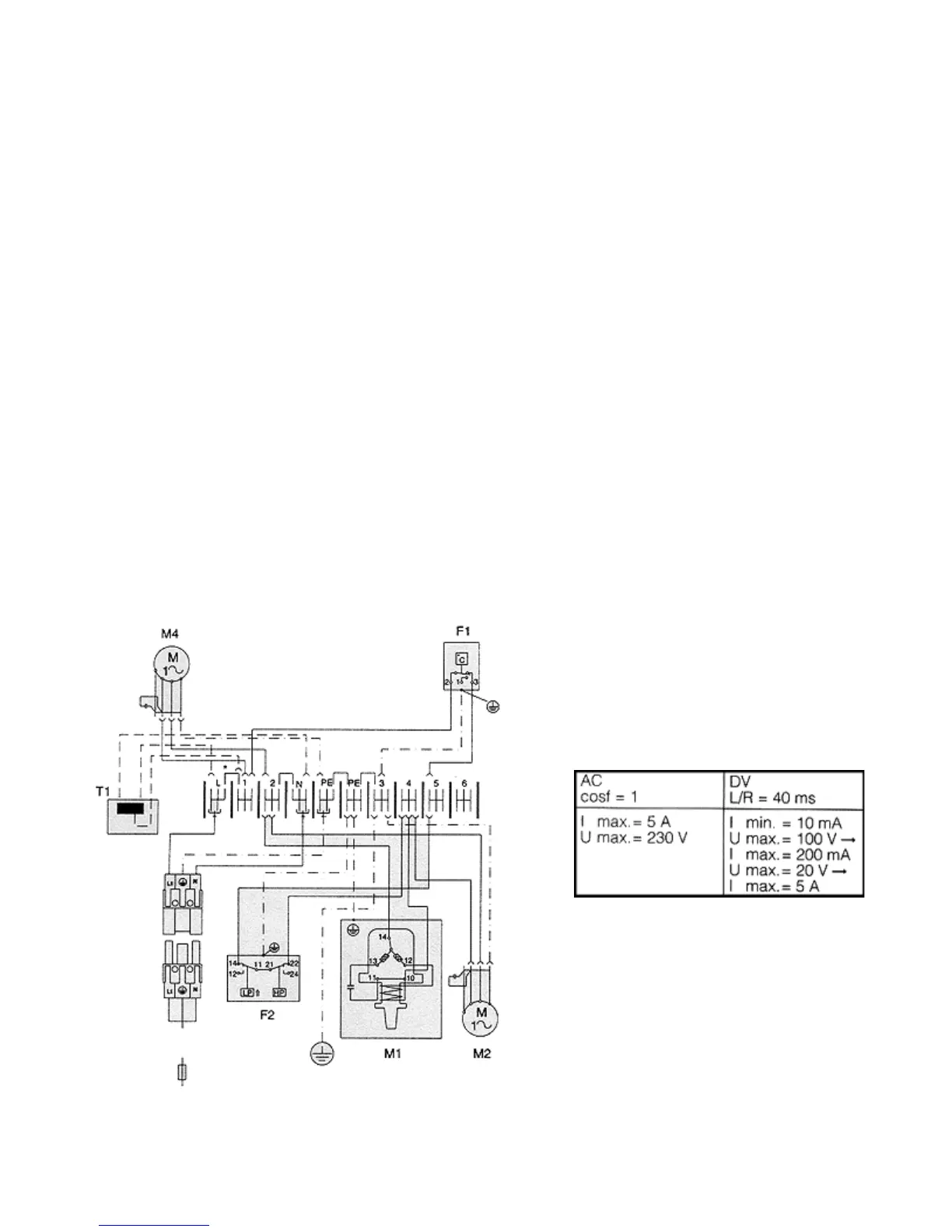
Wiring Diagram Microcontroller
A1=Power PCB
A2=Display Terminal
B1=Temperature sensor, internal temperature
B2=Temperature sensor, risk of icing
B3=Temperature sensor, external 1
B4=Temperature sensor, external 2
C1-C3=Operating capacitors
F1=Thermostat
F2=Pressostat
K1=Relay collective fault
M1=Compressor
M2=Condenser fan
M3=Condenser fan
M4=Evaporator fan
S2=Door limit switch (without door operated switch terminal 1, 2 open)
T1=Transformer (SK 3272100/3280100 and special units)
Electrical Connection by Customer:
X2=PLC interface (Sub-D-socket, 15-pole)
X10=Terminal strip
X10=L1, L2/N, PE=Mains connection
X10=1, 2=Door operated switch connection (supplied by customer)
X10=3, 4, 5=Collective fault message
Detailed Wiring Diagram:
Contact Data K1