Temperature Controller Driver
GP-Pro EX Device/PLC Connection Manual
243
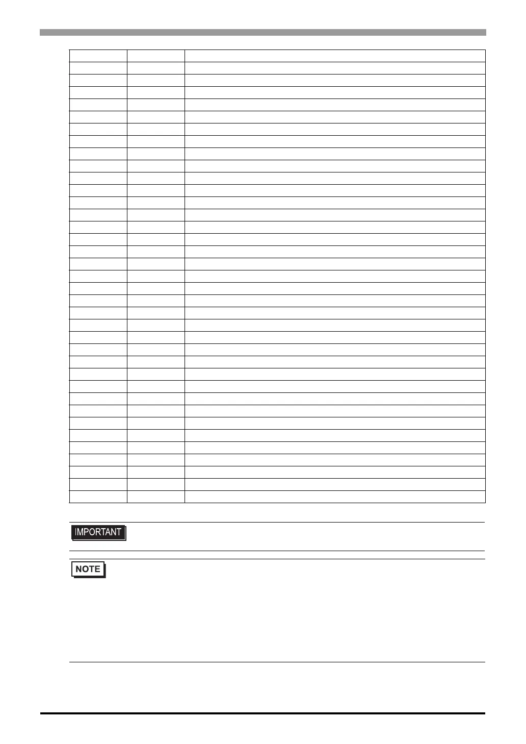
9A TI Number of Event DO extension alarm delay times [H-DO-C]
9B XL Cascade tracking [H-CIO-A]
9C KD Cascade data selection [H-CIO-A]
9D H3 Cascade DI function selection [H-CIO-A]
9E XJ TI input range number [H-TI-A/B/C]
9F F3 TI digital filter [H-TI-A/B/C]
A0 HI TI alarm 1 differential gap [H-TI-A/B/C]
A1 HJ TI alarm 2 differential gap [H-TI-A/B/C]
A2 XP TI alarm 1 type selection [H-TI-A/B/C]
A3 XQ TI alarm 2 type selection [H-TI-A/B/C]
A4 WE TI alarm 1 hold action [H-TI-A/B/C]
A5 WF TI alarm 2 hold action [H-TI-A/B/C]
A6 LF TI alarm 1 interlock [H-TI-A/B/C]
A7 LG TI alarm 2 interlock [H-TI-A/B/C]
A8 OC TI alarm 1 action at input error [H-TI-A/B/C]
A9 OD TI alarm 2 action at input error [H-TI-A/B/C]
AA DG Number of TI alarm delay times [H-TI-A/B/C]
AB R1 Event DI type selection 1 [H-DI-B]
AC R2 Event DI type selection 2 [H-DI-B]
AD R3 Event DI type selection 3 [H-DI-B]
AE R4 Event DI type selection 4 [H-DI-B]
AF E1 Event DI corresponding channel selection 1 [H-DI-B]
B0 E2 Event DI corresponding channel selection 2 [H-DI-B]
B1 E3 Event DI corresponding channel selection 3 [H-DI-B]
B2 E4 Event DI corresponding channel selection 4 [H-DI-B]
B3 W1 Event DI reversal selection 1 [H-DI-B]
B4 W2 Event DI reversal selection 2 [H-DI-B]
B5 W3 Event DI reversal selection 3 [H-DI-B]
B6 W4 Event DI reversal selection 4 [H-DI-B]
B7 LU Event DI logic circuit selection [H-DI-B]
B8 LW Event DI delay timer setting [H-DI-B]
B9 DH Number of HBA trigger points [H-CT-A]
BA FV Positioning adjustment counter [H-TIO-K]
BB VQ PCP module DI type selection [H-PCP-B]
BC H4 PCP module DI use selection [H-PCP-B]
BD VS PCP module DO de-energized selection [H-PCP-A, M-PCP-A (Z-190)]
• Setting "Use system data area" to GP-Pro EX system area result in improper
operation. Do not set "Use system data area."
• System area setting that can be used for the temperature controller is reading area size only. Please
refer to the GP-Pro EX Reference Manual for system data area.
Cf. GP-Pro EX Reference Manual "LS Area (Direct Access Method Area)"
• Please refer to the precautions on manual notation for icons in the table.
"Manual Symbols and Terminology"
• Even if non-existing address is used, there are cases when read error is not indicated. In this case,
zero (0) is kept for read out data. On the other hand, writing error is indicated.
Address Identifier Description

 Loading...


