Temperature Controller Driver
GP-Pro EX Device/PLC Connection Manual
252
6.11 REX-F Series
This address can be specified as system data area.
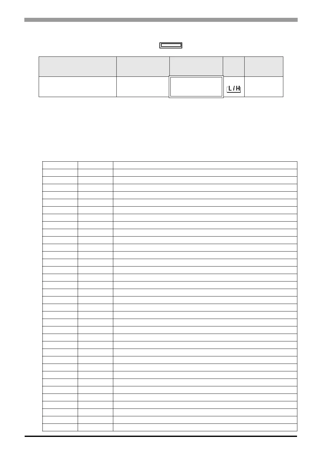
<Communication identifier list>
Device Bit Address Word Address
32
bits
Notes
Communication identifier 0000.0-0055.F 0000-0055
*1
*2
*1 There are cases for which writing is not available depending on the device address. Check the
identifying attributes of the external device’s manual before use.
*2 When bit is written, the indicator reads the corresponding word address of external device, assign
a bit to the read word address, and return to the external device. There are cases when correct data
cannot be written if the word address is written using a ladder program, while the indicator reads
data of the external device and sends it back.
Address Identifier Description
00 M1 Measured-value (PV) input
01 AA First alarm output
02 AB Second alarm output
03 AC Heater break alarm output
04 O1 Manipulated output (Heating-side)
05 O2 Manipulated output (Cooling-side)
06 B1 Burnout
07 B2 Feedback resistance (FBR) input burnout
08 S2 Remote setting value (RS)
09 M2 Feedback resistance input value (POS)
0A M3 Current transformer input value
0B MS Set-value (SV) monitoring
0C J1 Auto/manual transfer
0D C1 Local/remote transfer
0E E1 Local/external memory area transfer
0F ZA Control area No. transfer
10 G1 PID control/auto-tuning transfer
11 RA Local mode/computer mode identification
12 SR Operation execution (RUN)/STOP transfer
13 ON Manipulated output value (MV)
14 S1 Set-value (SV)
15 A1 First alarm setting
16 A2 Second alarm setting
17 P1 Proportional band (Heating-side)
18 I1 Integral time
19 D1 Derivative time
1A CA Control response designation parameter
1B P2 Cooling-side proportional band
1C V1 Deadband
1D HH Setting change rate limit
1E PB PV bias
1F F1 PV digital filter
20 DP PV low input cut-off
21 RR RS ratio
22 RB RS bias

 Loading...


