28
IMCD06-E2
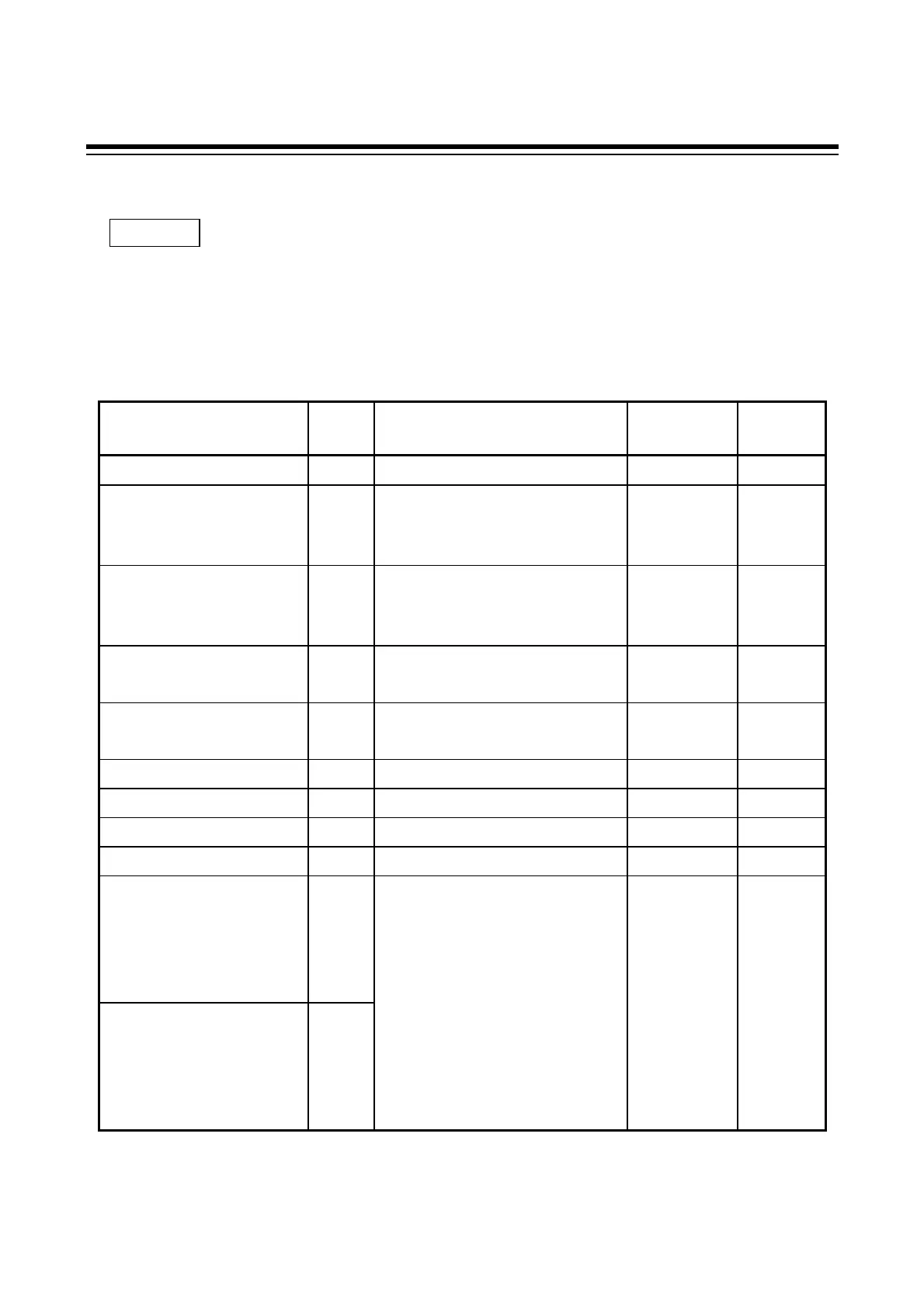
5. COMMUNICATION IDENTIFIER
Communication identifier list
Note that there are identifiers which indicate that communication is not possible depending on
the specification.
The number of digits is 6 for all data.
(Attributes RO: Read only, R/W: Read/Write )
Name
Iden-t
ifier
Data range
Factory set
value
Attribute
Measured value (PV)
M1
Within input range ---- RO
Current transformer input
1
See *1.
M2
0.0 to 100.0 A ---- RO
Current transformer input
2
See *2.
M3
0.0 to 100.0 A ---- RO
Alarm 1 status
See *3.
AA
0: OFF 1: ON ---- RO
Alarm 2 status
See *1.
AB
0: OFF 1: ON ---- RO
Burnout
B1
0: OFF 1: ON ---- RO
Error code
ER
0 to 255 See *4. ---- RO
RUN/STOP function
SR
0: RUN 1: STOP 0 R/W
Set value (SV)
S1
Within input range 0 R/W
Alarm 1 setting
See *3.
A1 Temperature input
Process alarm, deviation alarm,
SV alarm:
-1999 to +9999 °C [°F] or
-199.9 to +999.9 °C [°F]
Temperature
input:
50 or 50.0
R/W
Alarm 2 setting
See *1.
A2 Voltage/ current inputs
Deviation alarm: -span to +span
(Within 9999)
Process alarm, SV alarm:
Within input range
Voltage/
current
inputs: 5.0
Continued on the next page.
NOTES
 Loading...


