IMCD06-E2
5
3. SETTING FOR COMMUNICATION
In order to make communication between the CD101/CD401/CD501/CD701/CD901 digital
controller (hereinafter, the "controller") and the host computer, it is necessary to set the device
address, communication speed, data construction and interval time. Communication settings are made
in communication setting mode.
The following pictures used for explanation are for CD901. However, the same operation also applies
to other controllers. The section in each picture is dimly lit.
3.1 Transfer to communication setting mode
1. Turn on the power to this controller. Thus, the input type, input range and PV/SV display mode
change in this order.
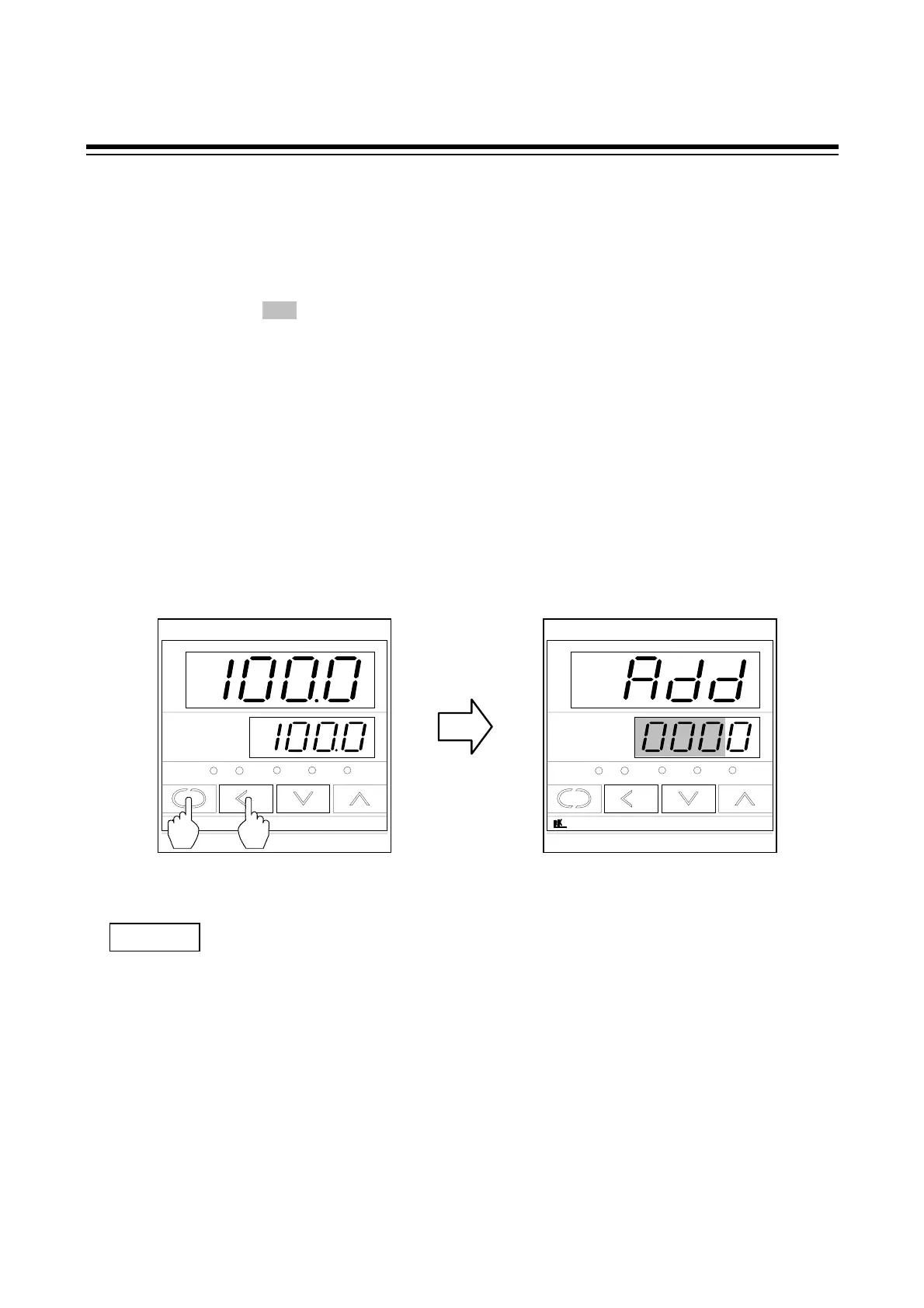
2. Pressing the <R/S key while the SET key is being pressed when PV/SV display mode is being
displayed selects communication setting mode. In this mode, device address "Add" are displayed
in the first place.
PV
SV
AT OUT1 OUT2 ALM1 ALM2
R/S
CD901
SET
PV
SV
AT OUT1 OUT2 ALM1 ALM2
R/S
CD901
SET
The communication setting mode can be selected anytime when the SV setting mode.
In order to terminate the communication setting mode, press the <R/S key while pressing the
SET key. After the communication setting mode terminates, the display changes to the PV/SV
display mode.
NOTES
Device address
Communication setting mode PV/SV display mode
 Loading...


