Telemetry-Box 2.4 GHz FASSTest
®
9
11. EXPLANATION, TELEMETRY DISPLAY
A:ON EDGE SPH/ ON
RECEIVER BATTERY
6.4V
MIN:
10.0V
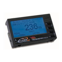
In its basic form the telemetry display is always the same; it
varies only according to the various sensors in use.
The "+" and "-" buttons are used to navigate through the
Display menu, as described in chapter 5.
Inordertokeepthelistofdisplaysshortandcomprehen-
sible, only the values of the active sensors are displayed,
and in the corresponding sequence (see chapter 14.3 /
Display).
EXAMPLE: "RECEIVER BATTERY" DISPLAY:
Sensor type display
Minimum voltage value
Name of the active model memory
SPH/ ON: Speech output ON
If you select this option, speech output is activated only for
the sensor which has been selected in the "Speech Out-
put" display (see page 10, chapter 12). The warnings for all
sensorsarealsogeneratedinspokenform.
MEL/ ON: Vario melody On
If "MEL/ On" is activated, only the vario tone and the war-
ning tones are shown.
AUD/ OFF: Audio tones Off
If you set the "AUD/ OFF" function, warnings only are ge-
neratedin spoken form;all otheraudio signalsare swit-
ched off.
Voltage display in Volt
Alarm messages On / Off
The alarm is switched on for the sensor type shown on the
screen. This function can be altered under "Warning dura-
tion" in the "Sensor set-up" menu.