4.8 DMX-512 connection/connection between xtures
The xture is equipped with both 3-pin and 5-pin XLR sockets for DMX input and output.The sockets are wired
in
parallel.
Only use a shielded twisted-pair cable designed for RS-485 and 3-pin or 5-pin XLR-plugs and connectors in
order to connect the controller with the xture or one xture with another.
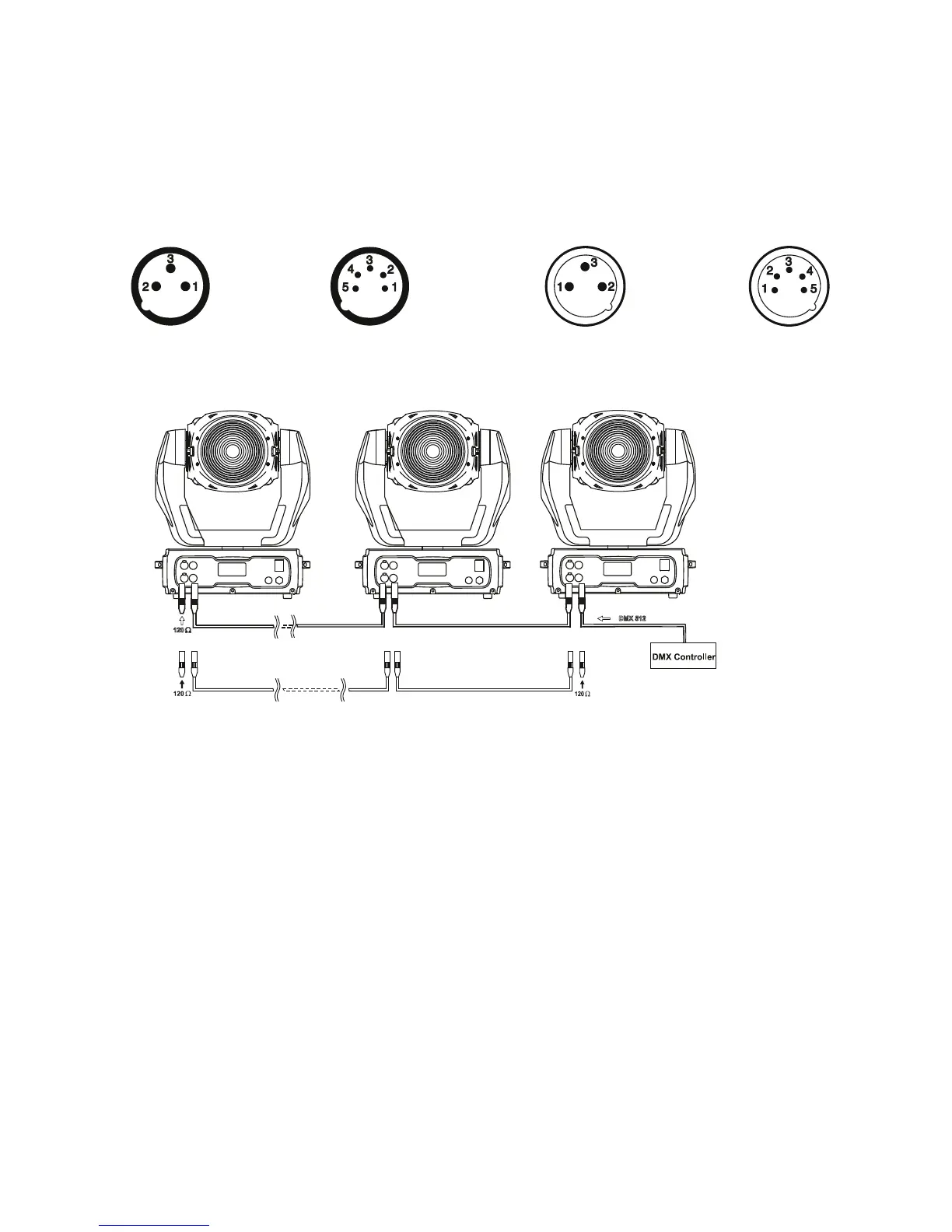
DMX - output DMX-input
XLR mounting-sockets (rear view): XLR mounting-plugs (rear view):
If you are using the standard DMX controllers, you can connect the DMX output of the controller directly with
the DMX input of the rst xture in the DMX-chain. If you wish to connect DMX-controllers with other XLR-out-
puts, you need to use adapter-cables.
Building a serial DMX-chain:
Connect the DMX-output of the rst xture in the DMX-chain with the DMX-input of the next xture. Always
connect one output with the input of the next xture until all xtures are connected.
Caution: At the last xture, the DMX-cable has to be terminated with a terminator. Solder a 120 Ω resistor
between Signal (–) and Signal (+) into a 3-pin XLR-plug and plug it in the DMX-output of the last xture.
Building a master/slave-chain:
Connect the DMX-output of the master xture in the data-chain with the DMX-input of the rst slave. Always
connect output with the input of the next slave until all slaves are connected (up to 9 xtures).
Caution:It’s necessary to insert the XLR termination plug (with 120 Ohm) into the input of the master xture
and into the output of the last slave xture in the link in order to ensure proper transmission on the data link.
Master/slave operation
Controller operation
1 - Shield
2 - Signal (-)
3 - Signal (+)
4 - Not connected
5 - Not connected
1 - Shield
2 - Signal (-)
3 - Signal (+)
4 - Not connected
5 - Not connected