8.
CARBURETOR
8-1
OPERATION
and
CONSTRUCTION
(See
Fig.
55
and
Fig.
56.)
8-1
-1
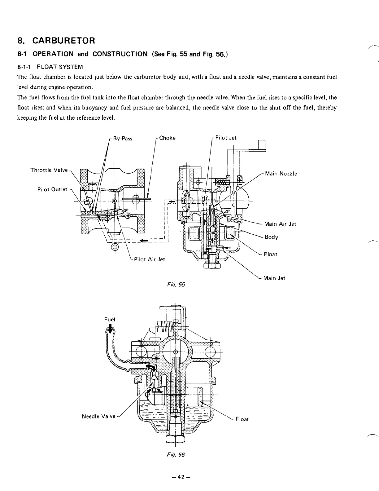
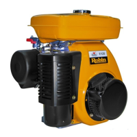
FLOAT SYSTEM
The float chamber
is
located just below the carburetor body and, with a float and a needle valve, maintains
a
constant fuel
level during engine operation.
The fuel
flows
from the fuel tank into the
float
chamber through the needle valve. When the fuel rises to a specific level, the
float rises; and when its buoyancy and fuel pressure are balanced, the needle valve close
to
the shut
off
the fuel, thereby
keeping the fuel at the reference level.
r
By-Pass Choke
,-
Pilot Jet
n
I
I
Throttle
Valve
Pilot Outlet
Needle
.
Main
Nozzle
Main
Air
Jet
Body
/-'-
Float
Main Jet
Fig.
55
Float
-
42
-