9-2-2
MEASURING INSULATION RESISTANCE
Refer to
8-4 MEASURING INSULATION RESISTANCE.
9-2-3
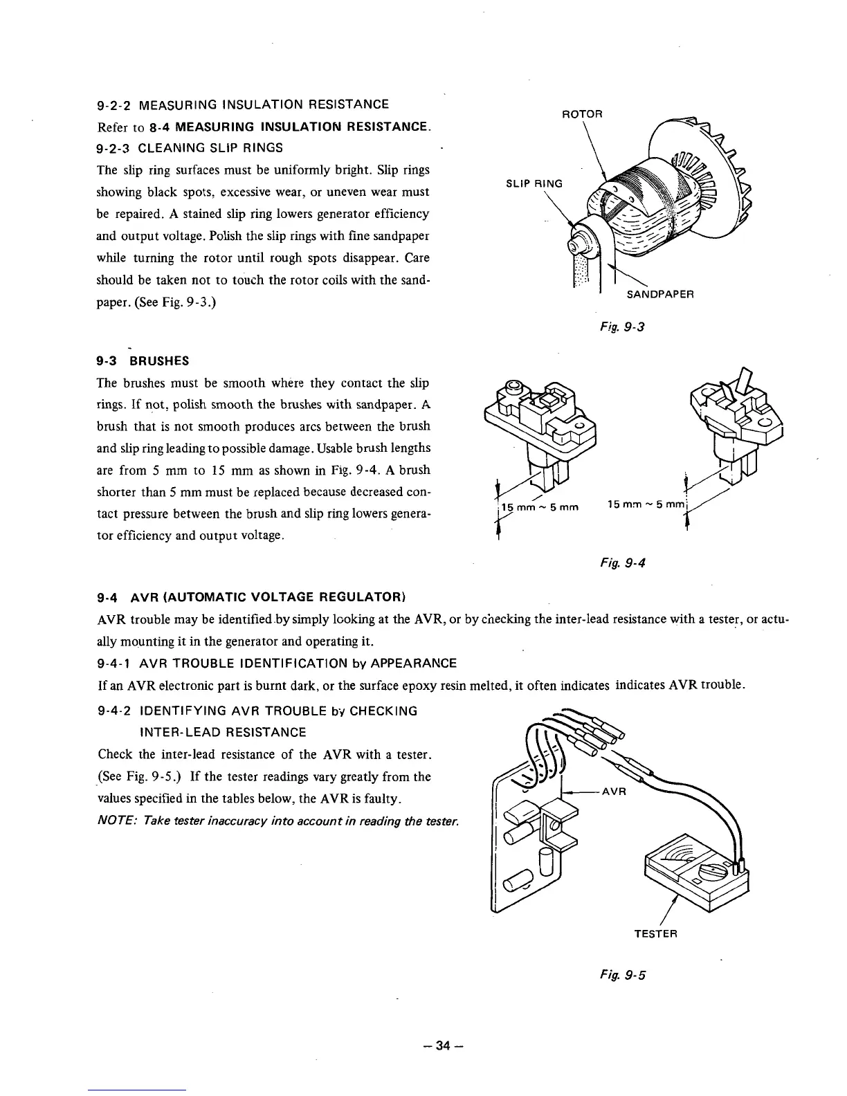
CLEANING SLIP RINGS
The slip ring surfaces must be uniformly bright. Slip rings
showing black spots, excessive wear, or uneven wear must
be repaired.
A
stained slip ring lowers generator efficiency
and output voltage. Polish the slip rings with fine sandpaper
while turning the rotor until rough spots disappear. Care
should be taken not to touch the rotor coils with the sand-
paper. (See Fig.
9
-3
.)
9-3 BRUSHES
The brushes must be smooth where they contact the slip
rings.
If
not, polish smooth the brushes with sandpaper.
A
brush that is not smooth produces arcs between the brush
and slip ring leading to possibie damage. Usable brush lengths
are from
5
mm to
15
mm as shown in Fig.
9-4.
A
brush
shorter than
5
mm must be replaced because decreased con-
tact pressure between the brush and slip ring lowers genera-
tor efficiency and output voltage.
Fig.
9-3
f
i15mm-5mm
15m.m-5m
Fig.
9-4
9-4 AVR (AUTOMATIC VOLTAGE REGULATOR)
AVR
trouble may be identified.by simply koking at the
AVR,
or by checking the inter-lead resistance with a tester, or actu-
ally mounting it in the generator and operating it.
9-4-1
AVR TROUBLE IDENTIFICATION
by
APPEARANCE
If
an
AVR
electronic part is burnt dark,
or
the surface epoxy resin melted, it often indicates indicates
AVR
trouble.
9-4-2
IDENTIFYING AVR TROUBLE
bf
CHECKING
INTER-LEAD RESISTANCE
Check the inter-lead resistance
of
the
AVR
with a tester.
(See Fig.
9-5.)
If the tester readings vary greatly from the
values specified in the tables below, the
AVR
is faulty.
NOTE:
Take tester inaccuracy into account in reading the tester.
TESTER
Fig.
9-5
-34-