10-3-7
RUBBER MOUNTS
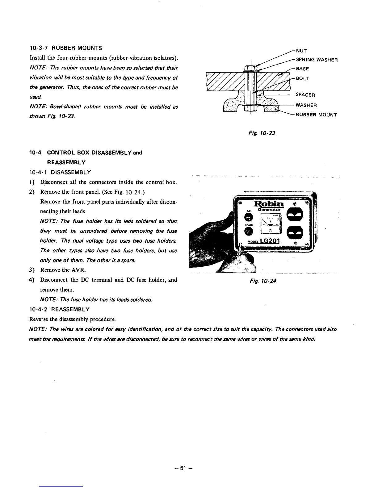
Install the four rubber mounts (rubber vibration isolators).
NOTE: The rubber mounts have been
so
selected that their
vibration will be most suitable to the type and frequency of
the generator. Thus, the ones of the correct rubber must be
used.
NOTE: Bowl-shaped rubber mounts must be installed as
shown
Fig.
10-23.
+
RUBBER
MOUNT
Fig.
10-23
10-4
CONTROL
BOX
DISASSEMBLY
and
REASSEMBLY
10-4-1
DISASSEMBLY
-~
~~ ~ ~
1)
Disconnect
all
the connectors inside the control
box.
~~~
.
~
~.
.~~
3)
Remove the front panel. (See Fig.
10-24.)
Remove the front panel parts individually after discon-
necting their leads.
NOTE: The fuse holder has
its
leds soldered
so
that
they must be unsoldered before removing the fuse
holder. The dual voltage type
uses
two fuse holders.
The other types also have two fuse holders, but use
only one of them. The other
is
a spare.
Remove the
AVR.
4)
Disconnect the
DC
terminal and
DC
fuse holder, and
Fig.
10-24
remove them.
NOTE: The fuse holder has
its
leads soldered.
10-4-2
REASSEMBLY
Reverse the disassembly procedure.
NOTE: The wires are colored for easy identification, and of the correct size to suit the capacity. The connectors used also
meet the requirements.
If
the wires are disconnected,
be
sure to reconnect the same wires or wires
of
the Same kind.
-
51
-