10-3
HOW
TO
REASSEMBLE
10-3-1
FRONT
COVER
1)
Reassemble the handle and front cover.
*LG072:
69
x
15
mm bolt
.
.
.2
pcs.
*Others:
8Q
x
18 mm bolt
.
.
.3
pcs.
2)
Install the front cover
on
the engine main bearing cover,
engaging the faucet joint and making sure that the han-
dle is up.
*LG072:
60
x
18
mm bolt
.
.
.4 pcs.
Tightening torque
48
to
60
kg-cm
*Others:
89
x
18
mm bolt
.
.
.4 pcs.
Tightening torque
120
to 140 kg-cm
..
~.~
~ ~
"~
.
.
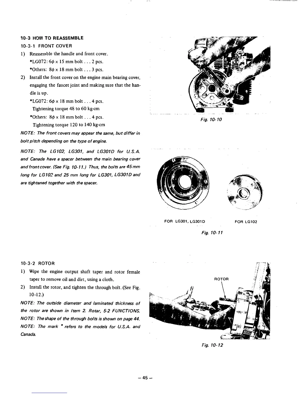
NOTE: The front covers may appear the same, but differ in
bolt pitch depending on the type of engine.
NOTE: The LG102, LG301, and LG301D for
U.S.A.
and Canada have a spacer between the main bearing cover
and frontcover. (See Fig. 10- 1
1.)
Thus, the bolts are 45mm
long for LG
102
and
25
mrn long for
L
G301,
L
G301
D
and
are tightened together with the spacer.
~~.
.
FOR
LG301, LG301
D
FOR
LG102
Fig. 10- 1
1
10-3-2
ROTOR
-.
~.?
..
.
1) Wipe the engine output shaft taper and rotor female
taper to remove oil and dirt, using a cloth.
2)
Install the rotor, and tighten the through bolt. (See Fig.
10-12.)
NOTE: The outside diameter and laminated thickness of
the rotor are shown in Item
2.
Rotar,
5-2
FUNCTIONS.
NOTE: Theshape of the through bolts is shown on page 44.
NOTE: The mark
refers to the models for
U.S.A.
and
Canada.
Fig.
10-
12
-45
-