8-2
AC OUTPUT MEASURING
TO
A
Fig.
8-
7
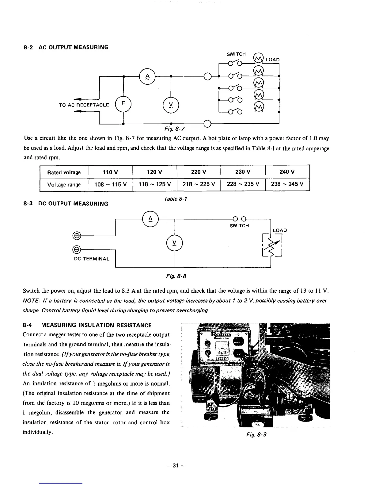
;e a circuit like the one shown in Fig.
8-7
for measuring
AC
output.
A
hot plate or lamp with
a
power factc
)r
of
1
.O
may
be used as a load. Adjust the load and rpm, and check that the voltage range is as specified in Table
8-1
at the rated amperage
and rated rpm.
Ratedvoltage
I
11OV
1
12OV
1
22OV 230V
238-245V
Voltagerange
'
108-115V
j
118-125V
I
218-225V
1
228-235V
I
240
V
I
8-3
DC OUTPUT MEASURING
Table
8-
1
00
SWITCH
@
DC
TERMINAL
Fig.
8-8
Switch the power on: adjust the load to
8.3
A
at the rated rpm, and check that the voltage is within the range of
13
to
11
V.
NOTE: If
a battery
is
connected as the load, the ouwut voltage increases by about
1
to
2
V,
possibly causing battery over-
charge. Control battery liquid level during charging to prevent overcharging.
8-4
MEASURING INSULATION RESISTANCE
Connect a megger tester to one of the two receptacle output
terminals and the ground terminal, then measure the insula-
tion resistance.
(Ifyourgenerator is the no-fise breaker type,
close the no-fuse breakerand measure it. If yourgenerator
is
the dual voltage type, any voltage receptacle may be used.)
An
insulation resistance of
1
megohms or more is normal.
(The original insulation resistance at the time of shipment
from the factory is
10
megohms or more.) If it is less than
1
megohm, disassemble the generator and measure the
insulation resistance of tne stator, rotor and control box
individually.
Fig.
8-9
-
31
-