9-6
RECEPTACLE
and
AC PLUG
Check the current-carrying parts
of
the receptacles and AC plugs and their leads and plastic parts
for
bums.
9-7
VOLTMETERS
Apply AC voltage to a terminal and check if the voltmeter
reads normal.
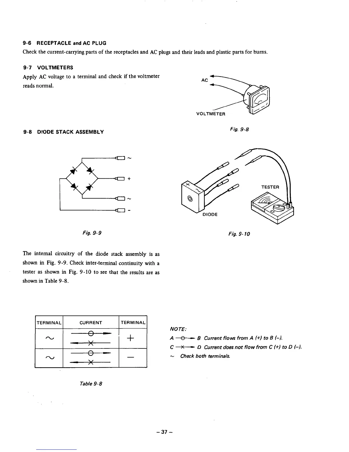
9-8
DIODE STACK ASSEMBLY
"
Fig.
9-9
The internal circuitry of the diode stack assembly is as
shown
in
Fig.
9-9.
Check inter-terminal continuity with a
tester as shown in Fig.
9-10
to see that the results are as
shown in Table
9
-8.
VOLTMETER
Fig.
9-8
/_1
-I
+I
--"--I
Fig.
9-
10
NOTE:
A
$
B
Current flows from
A
(+)
to
B
6).
C
++"
D
Current does not flow
from
C
(+I
to
D
(-1.
-
Check both terminals.
Table
9-8
-37
-