THE FOLLOWING APPLY
TO
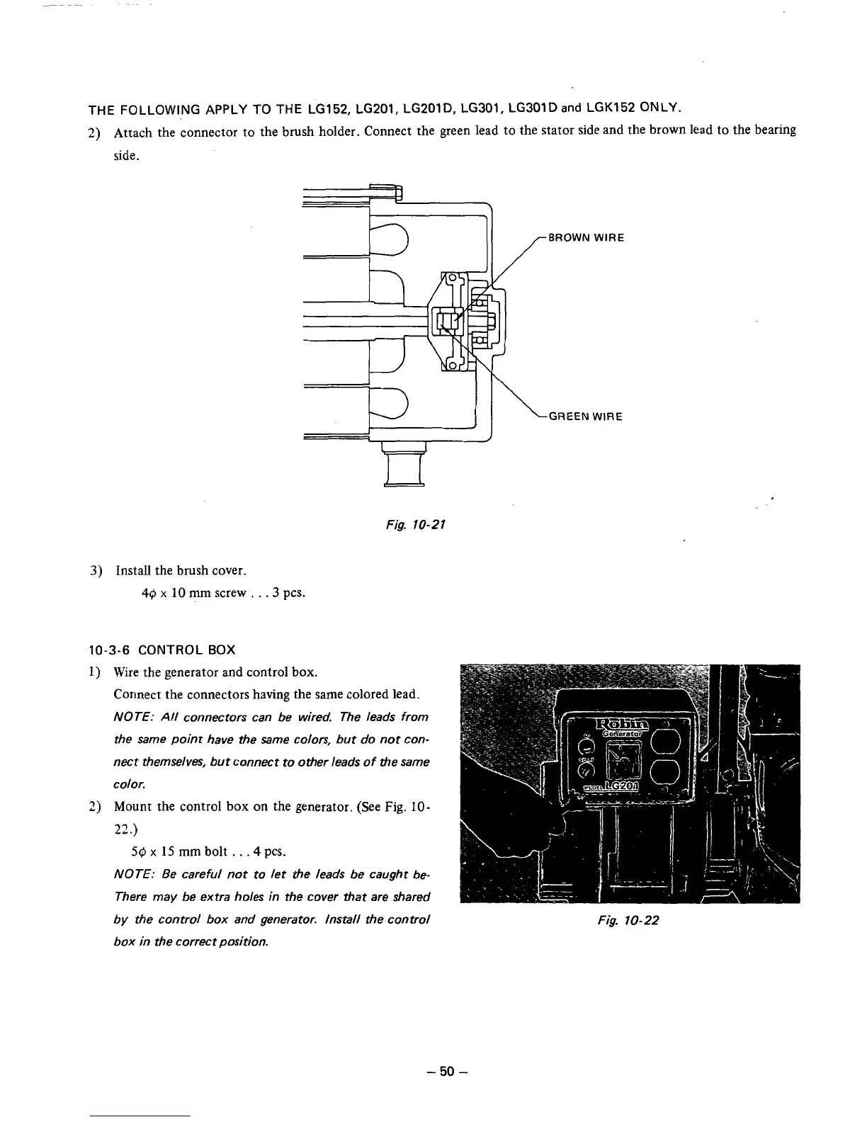
THE LG152, LG201, LG201D. LG301, LG3OlD
and
LGK152
ONLY.
2)
Attach the connector
to
the brush holder. Connect the green lead to the stator side and the brown lead to the bearing
side.
271
BROWN WIRE
GREEN WIRE
Fig. 10-21
3)
Install the brush cover.
40
x
10
mm
screw
.
.
.3
pcs.
10-3-6 CONTROL
BOX
1
j
Wire the generator and control box.
Connect the connectors having the same colored lead.
NOTE:
All
connectors can be wired. The leads from
the same point have the same colors, but
do
not
con-
nect themselves, but connect to other leads
of
the same
color.
2j
Mount the control box
on
the generator. (See
Fig.
10-
27,
.)
59
x
15
mm bolt
. .
.4
pcs.
NOTE: Be careful not to let the leads be caught be-
There may be extra holes in the cover that are shared
by the control box and generator. Install the control
box in the correct position.
Fig.
10-22
-
50
-