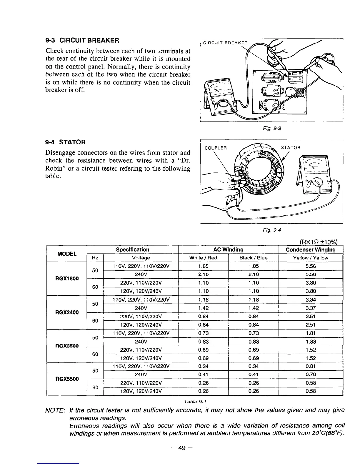
9-3 CIRCUIT BREAKER
Check continuity between each of two terminals
at
the rear of the circuit breaker while it is
mounted
on the control panel. ISormally, there is continuity
between each of the two when the circuit breaker
is on while there is no continuity when the circuit
breaker is off.
9-4 STATOR
Disengage connectors on the wires from stator and
check the resistance between wires with a “Dr.
Robin” or a circuit tester refering to the following
table.
Fig. 9-3
i
COUPLER
Fig. 9-4
Table 9- 1
NOTE: If the circuit tester is not sufficiently accurate, it may not show the values given and may give
erroneous readings.
Erroneous readings will also occur when there is a wide variation of resistance among coil
windjngs or when measurement is performed at ambient temperatures different from 2O”C(68”F).
- 49 -