9. CHECKING FUNCTIONAL MEMBERS
9-1 PILOT LAMP and VOLTMETER
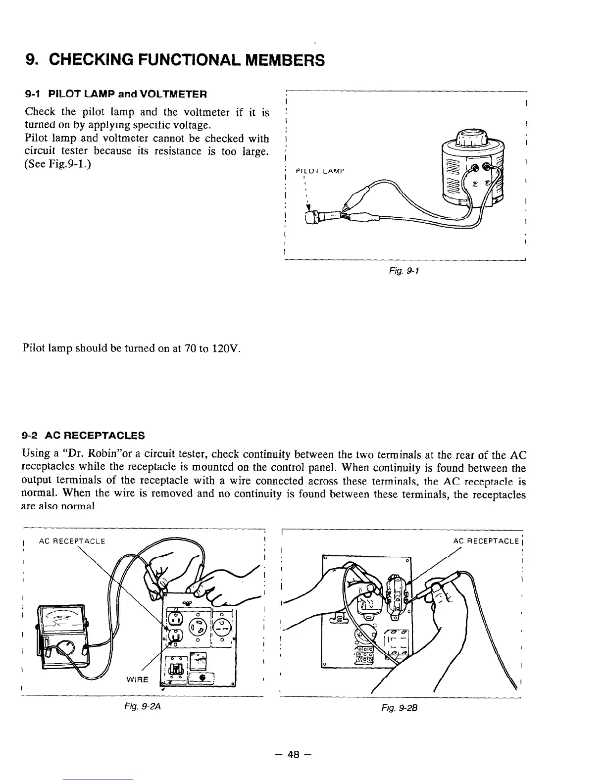
Check the pilot lamp and the voltmeter if it is
turned on by applying specific voltage.
Pilot lamp and voltmeter cannot be checked with
circuit tester because its resistance is too large.
(See Fig.9-1.)
PILOT LA’vlP
I
Fig. 9-7
Pilot lamp should be turned on at 70 to 120V.
9-2 AC RECEPTACLES
Using a “Dr. Robin”or a circuit tester, check continuity between the two terminals at the rear of the AC
receptacles while the receptacle is mounted on the control panel. When continuity is found between the
output terminals of the receptacle with a wire connected across these terminals, the AC receptacle is
normal. When the wire is removed and no continuity is found between these terminals, the receptacles
are also normal.
I
I
I
I
I
I
I
I
.
AC RECEPTACLE i
Fig. 9-2A
- 48 -
F/g. 9-28