9-5 ROTOR ASSEMBLY
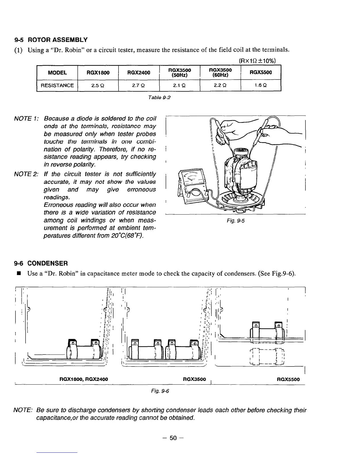
(1) Using a “Dr. Robin” or a circuit tester, measure the resistance of the field coil at the terminals.
(RXlQ &lo%)
MODEL RGX1800
RGX2400 !
RGX3500
(50Hz) ;
RGX3500 )
(60Hz) : RGX6600
RESISTANCE 2.5 Q
2.7 R 2.1 a
2.2 Q 1.6R
Table 9-2
NOTE 1: Because a diode is soldered to the coil
ends at the terminals, resistance may
be measured only when tester probes
touche the terminals in one combi-
nation of polarity. Therefore, if no re- i
sistance reading appears, try checking
in reverse polarity.
I
NOTE 2: If the circuit tester is not sufficiently
accurate, it may not show the values
given and may give erroneous
readings.
Erroneous reading will also occur when !
there is a wide variation of resistance
among coil windings or when meas-
Fig. 9-5
urement is performed at embient tem-
peratures different from 20°C(68”F).
9-6 CONDENSER
1 Use a “Dr. Robin” in capacitance meter mode to check the capacity of condensers. (See Fig.9-6).
/ ,I.
$:
i:I
:,: ‘8
j;‘I i
I! , I
!
I
II .I’
RGX1800. RGX2400 RGX3500 ,
RGX5500
Fig. 9-6
NOTE: Be sure to discharge condensers by shorting condenser leads each other before checking their
capacitance,or the accurate reading cannot be obtained.
- 50 -