27
4.4 Coupling
4.4.1 Direct coupling
Slide the half couplings onto the shaft of the blower and of the motor using suitable tools.
Warning: Do not use a hammer to slide on the half couplings.
Secure the half couplings with security dowels which will push on the keys.
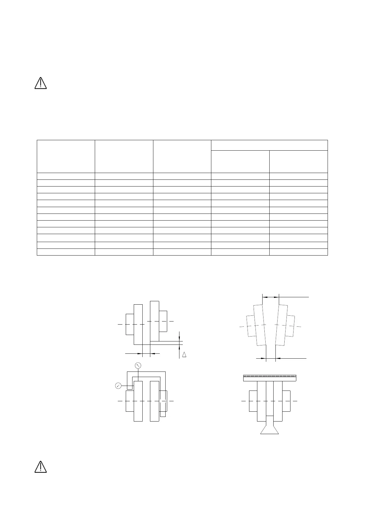
Place the blower at the distance S from the motor as indicated in the table below.
Align the shafts of the blower and of the motor by shims under the feet of the motor and/or blower.
Check the alignment by using comparators or gauges with scales as shown in Fig. 6
Standard deviation
Coupling
diameter
Distance
S
( mm )
Axial
deviation
Ka
( mm )
Radial
Kr
( mm )
Angular
Kw
( mm )
80 3 1 0.13 0.13
100 3 1 0.15 0.15
130 3 1 0.18 0.18
150 3 1 0.21 0.21
160 4 2 0.27 0.27
180 4 2 0.30 0.30
200 4 2 0.34 0.34
225 4 2 0.38 0.38
250 5.5 2.5 0.42 0.42
280 5.5 2.5 0.47 0.47
315 5.5 2.5 0.52 0.52
350 5.5 2.5 0.58 0.58
Alignment check
Smax < S + Ka
Smin < S – Ka
rpm
Kv = 1.5 -------------
3000
Dr < Kr x Kv
Dw < Smax – Smin
Dw < Kw x Kr
Dr + Dw < Kw x Kv
Fig. 6
Warning : Alignment errors cause premature wearing of the bearings and flexible couplings.
r
S
S Min
 Loading...