16
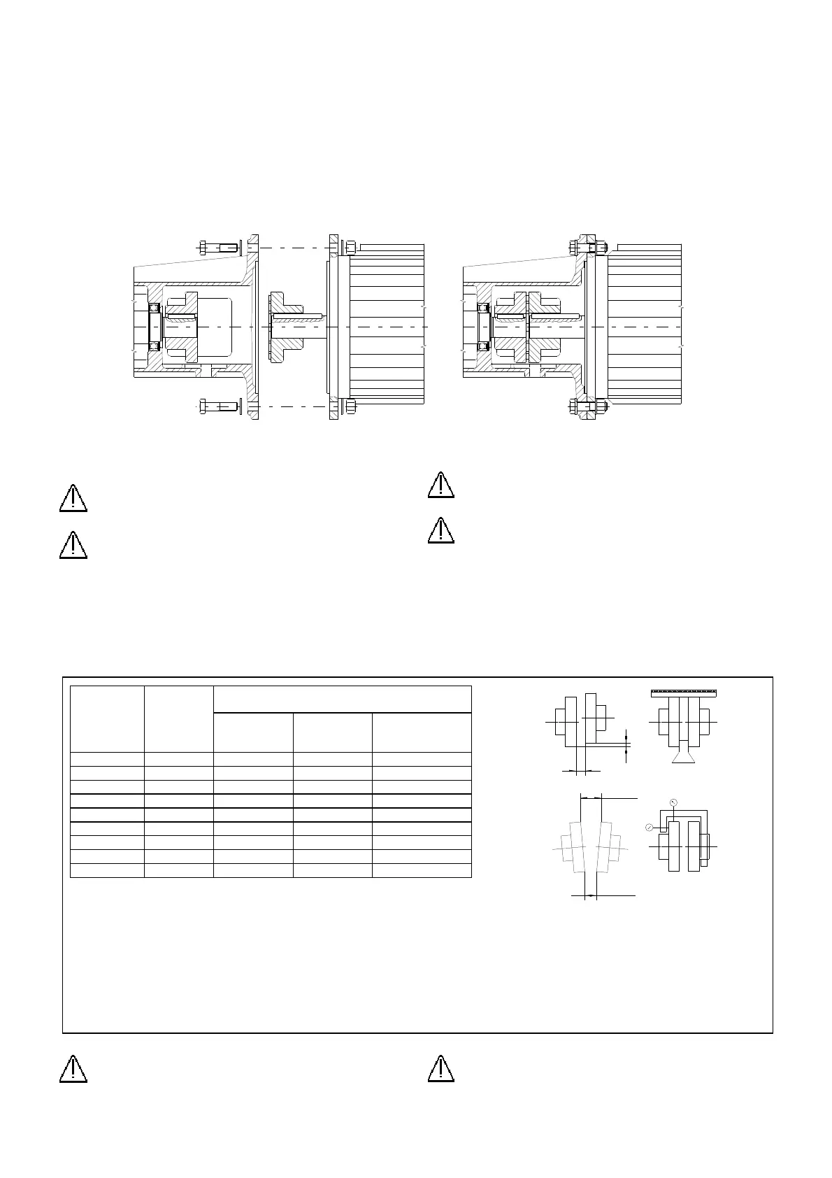
Fig.10
Fig.11
Diametro
giunto
Couplig
diameter
(mm)
Distanza
Distance
S (mm)
Scostamenti base per giunti elastici
Base deviations for elastic coupling
Assiale
Axial
Ka (mm)
Radiale
Radial
Kr (mm)
Angolare
Angular
Kw (mm)
130 3 1 0.18 0.18
150 3 1 0.21 0.21
160 4 2 0.27 0.27
180 4 2 0.30 0.30
200 4 2 0.34 0.34
225 4 2 0.38 0.39
250 5.5 2.5 0.42 0.42
280 5.5 2.5 0.47 0.47
315 5.5 2.5 0.52 0.52
dR
dW=Smax-Smin
S min
S max
S
Tab. 7
Il coefficiente di velocità vale -
The speed factor is equal to
:
Dove – Where: n=velocità – speed (RPM)
Gli scostamenti assiali misurati devono risultare - The axial deviations must be: S
max
≤ S+Ka S
min
≤S-Ka
Lo scostamento radiale deve risultare - The radial deviations must be: dR≤Kr Kv
Lo scostamento angolare deve risultare - The angular deviations must be: dW≤Kw Kv
Deve risultare anche – Must result also: dR+dW≤Kw Kv
4.5 Accoppiamento
Le pompe monoblocco /M (grandezze 3÷16) sono montate
direttamente sulla flangia del motore elettrico.
Per le pompe con supporto /SG (grandezze 7÷21) il motore elettrico
è montato sul supporto comune pompa-motore mediante
accoppiamento con giunto elastico (par.4.5.1).
Per le pompe delle grandezze 23÷60 bisogna prevedere un
basamento comune ed è possibile realizzare un accoppiamento
diretto con giunto (par.4.5.2) al motore elettrico o un accoppiamento
con trasmissione a cinghia (par.4.5.3).
4.5.1 Accoppiamento con giunto per versioni /SG
Pulire perfettamente il centraggio della flangia della pompa e del
motore elettrico da eventuale sporcizia o residui di verniciatura.
Allineare i semigiunti ai rispettivi alberi.
Accoppiare
il motore
alla pompa
e serrare i
bulloni
delle flange
come
indicato
anche in
fig.10.
4.5.2
Accoppia
mento con
giunto
Infilare i
semigiunti
sull’albero
della pompa e del motore elettrico servendosi di opportuni attrezzi
introduttori.
Attenzione: Non utilizzare il martello per infilare i
semigiunti.
Attenzione: Proteggere il giunto rotante con apposito
riparo
Fissare i semigiunti con grani filettati agenti sulle linguette. Applicare i
grani con adesivo frenafiletti
Accostare la pompa ed il motore alla distanza S indicata in tab.7.
Allineare gli alberi della pompa e del motore inserendo opportuni
spessori sotto i piedi del motore o della pompa.
Controllare l’allineamento mediante comparatori o spessimetri a
righello come indicato in fig.11.
Attenzione: Gli errori di allineamento causano l’usura
prematura dei cuscinetti e del giunto elastico.
4.5 Coupling
The close coupled pumps /M version (sizes 3, 16) are directly
coupled to the electric motor flange.
For pumps with bearing bracket /SG version (sizes 7, 21) the electric
motor is assembled to the bracket and the coupling is made with
empty shaft drive (par. 4.5.1).
The pumps sizes 23,25,30,40,60 need a base-plate, common with
the electric motor, and it is possible to drive the pumps directly with
flexible coupling (par. 4.5.2) or by v-belt drive (par. 4.5.3).
4.5.1 Direct flexible coupling for /SG version
Clean perfectly the inside of the pump and motor flanges and remove
dust and paint residuals.
Align half-couplings to their respective shafts and secure the half
couplings with
security
dowels, which
will push on
the keys.
Fit the motor
to the pump
and fix the
flange bolts as
shown in fig.
10.
4.5.2 Direct
flexible
coupling
Slide the half
couplings into
the shaft of the
pump and of the motor using suitable tools.
Warning: Do not use a hammer to slide on the half
couplings.
Warning: Protect the coupling with proper protection
Secure the half couplings with security dowels, which will push on the
keys. Apply dowels with thread locking adhesive.
Place the pump at the distance S from the motor as indicated in tab.
7. Align the shafts of the pump and of the motor and, where
necessary, insert shims under the feet of the motor and/or of the
pump.
Check the alignment by using comparators or gauges with scales as
shown in fig. 11.
Warning: Alignment errors cause premature wearing of
bearings and flexible coupling.
 Loading...