18
5 ESERCIZIO
5.1 Controlli prima dell’avviamento
Prima di mettere in funzione la pompa eseguire i seguenti controlli:
-Assicurarsi che le tubazioni siano state pulite internamente e che
eventuali ostruzioni siano state rimosse.
-Assicurarsi che la pompa e il motore siano stati correttamente
allineati.
-Assicurarsi che tutte le connessioni fra tubazioni e pompa siano
state correttamente serrate e sigillate.
-Assicurarsi che la pompa giri liberamente a mano; in caso contrario
sbloccarla facendo leva sul mozzo del giunto della pompa o per le
versioni /M e /SG servirsi dell’attacco filettato presente sull’albero lato
posteriore del motore elettrico.
-Assicurarsi di aver inserito tutte le protezioni di sicurezza.
5.2 Preparazione
-Aprire completamente l’eventuale valvola di intercettazione posta sul
condotto di mandata.
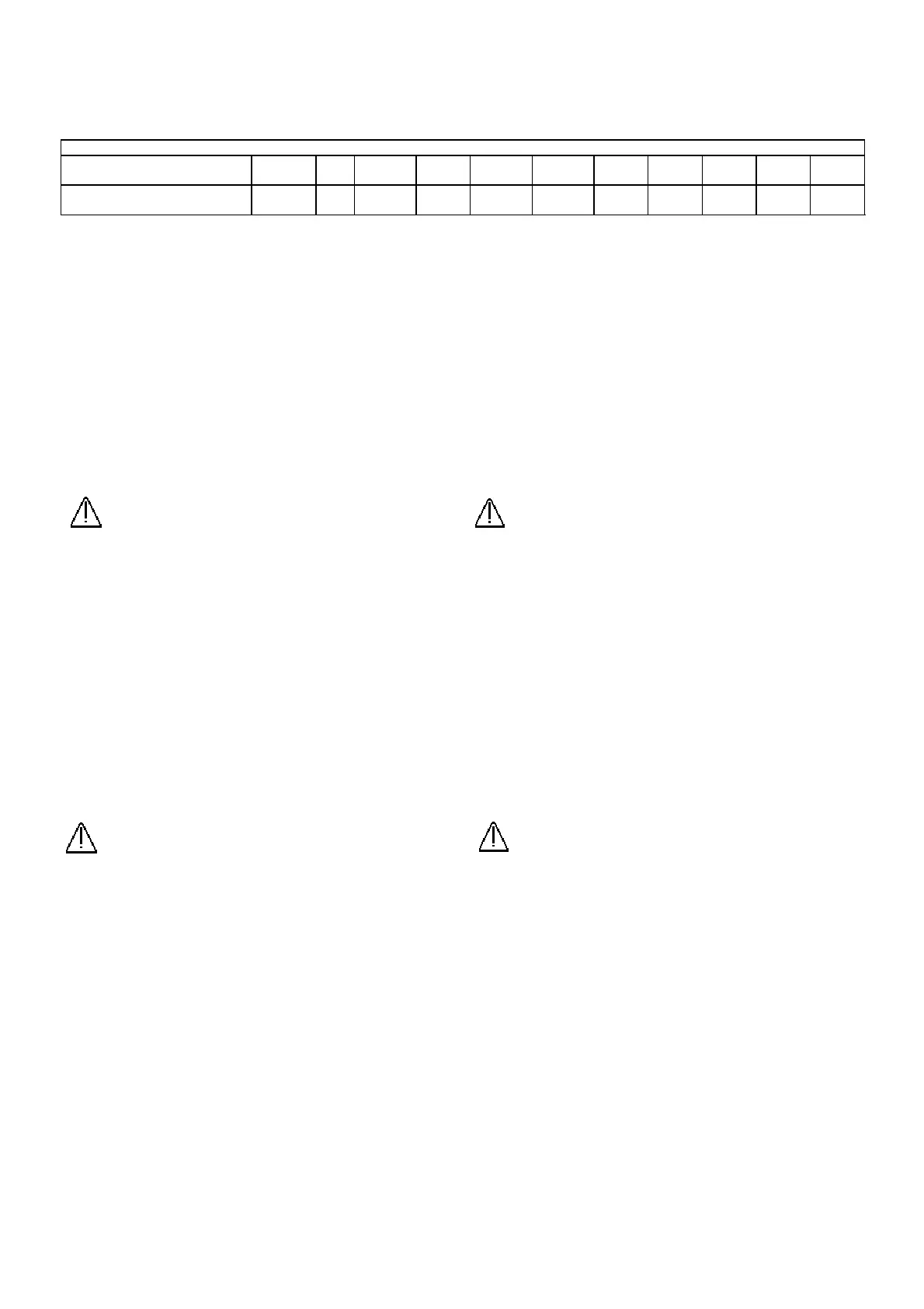
-Riempire la pompa attraverso il tappo di riempimento o la flangia di
aspirazione sino alla mezzeria dell’albero. In tab.10 sono indicati i
quantitativi di liquido necessario per compiere questa operazione.
Per le pompe munite di valvola VAD il liquido inizierà a fuoriuscire da
quest’ultima a riempimento avvenuto.
Attenzione: Avviamenti con pompa troppo piena di
liquido di servizio possono danneggiare gravemente la
pompa.
-Controllare il senso di rotazione della pompa avviandola per breve
tempo e verificando che il senso di rotazione della ventola del motore
sia orario; in caso contrario togliere tensione al circuito di
alimentazione elettrica e ripristinare i collegamenti del motore
elettrico invertendo la posizione di due fasi.
5.3 Primo avviamento
Con riferimento allo schema di installazione di fig.9(a):
-Aprire la valvola di intercettazione 8.
-Avviare la pompa:
1) Alimentazione automatica:
- l’elettrovalvola 5, si apre all’avviamento del motore elettrico.
2) Alimentazione manuale :
- aprire la valvola di by-pass 6 subito dopo l’avviamento della
pompa.
-Regolare la portata del liquido di servizio (vedi tab.11-par.5.6)
mediante la valvola di regolazione 4. Misurare il valore della portata
per mezzo del flussimetro 3 o misurando la quantità di servizio
scaricata dalla pompa (solo se funziona in vuoto).
-Eseguire i controlli di funzionamento come indicato al par.5.5.
Attenzione: L’ esercizio in assenza di alimentazione del
liquido di servizio può danneggiare gravemente la
pompa.
5.4 Avviamenti successivi
Ripetere le operazioni eseguite al primo avviamento controllando
sempre il livello di riempimento iniziale come indicato nella
preparazione.
5.5 Controlli in esercizio
Durante l’esercizio della pompa è bene ricordare che:
-Le variazioni brusche delle pressioni di aspirazione o di mandata
causano ingolfamento della pompa che si manifesta con elevati
assorbimenti di corrente e vibrazioni.
-La portata del liquido di servizio e la sua temperatura influenzano le
prestazioni della pompa (basse portate e temperature elevate fanno
diminuire la portata di gas aspirato
5. OPERATION
5.1 Controls before start-up
Before starting up the pump the following operations and checks
should be carried out:
- Check if the pipes have been internally cleaned and if obstructions
have been removed.
- Verify the alignment between motor and pump.
- Check that all the connections between pump and pipes are
tightened and sealed.
- Check that the shaft rotates freely by hand. If the pump is locked,
use lever acting on the elastic coupling of the pump.
To unlock the close coupled version (/M, /SG) use the threaded hole
present on the fan side on the motor shaft.
- Check that all the safety protections are enabled.
5.2 Preparation
- Open the shut-off valve (if installed) on the discharge piping.
- Fill the pump through the filling plug or the suction flange until the
liquid reaches the pump shaft level. Tab.10 shows the quantities of
liquid to carry out this operation.
For pumps provided with VAD valve the liquid flows out from the
valve when the correct level is reached.
Warning: Start-up with incorrect filling of service liquid
may cause serious damages to the pump.
- Check the direction of rotation by starting-up the pump for a short
time and check that the motor fan rotates clock-wise; if the direction
is not correct turn off the electric supply and invert connections of
the two motor conductors.
5.3 First start-up
Refer to the installation diagram of fig. 9 (a):
- Open shut off valve 8
- Start-up the pump
1) Automatic supply:
- Solenoid valve 5, actuated by electric motor, opens when the
motor starts.
2) Manual supply:
- Open the by-pass valve 6 right after starting the pump.
- Adjust the service liquid flow rate (see tab.11-par. 5.6) by means of
the regulation valve 4. Measure the flow rate value by means of the
flow meter 3 or, if missing, by measuring the service liquid flow rate
from discharge pipe of the pump (only for vacuum
operation).
- Execute operating checks as indicated at par. 5.5.
Warning: Operation without service liquid supply may cause
serious damages to the pump.
5.4 Next start-up
Execute the operations carried out at first start-up and check the
correct level of the service liquid into the pump.
5.5 Checks during operation
During operation it is important to remember the following points:
- Fast pressure variation floods the pump and may increase power
absorption and vibrations.
- The pump capacity changes depending on the flow rate and the
temperature of the service liquid (for low flow and high temperature
the capacity decreases or the pressure
uantità di liquido all’avviamento
Liquid quantity before start
Pump size
3 7 14 16 17 21 23 25 30 40 60
Quantità ( l )
Quantity
0.25 1 1.3 2 2.6 3.7 6 8 15 24 95
 Loading...