25
Once the boiler has been secured with the
hanging brackets to the wall and the required
holes have been made to allow the ue to exit
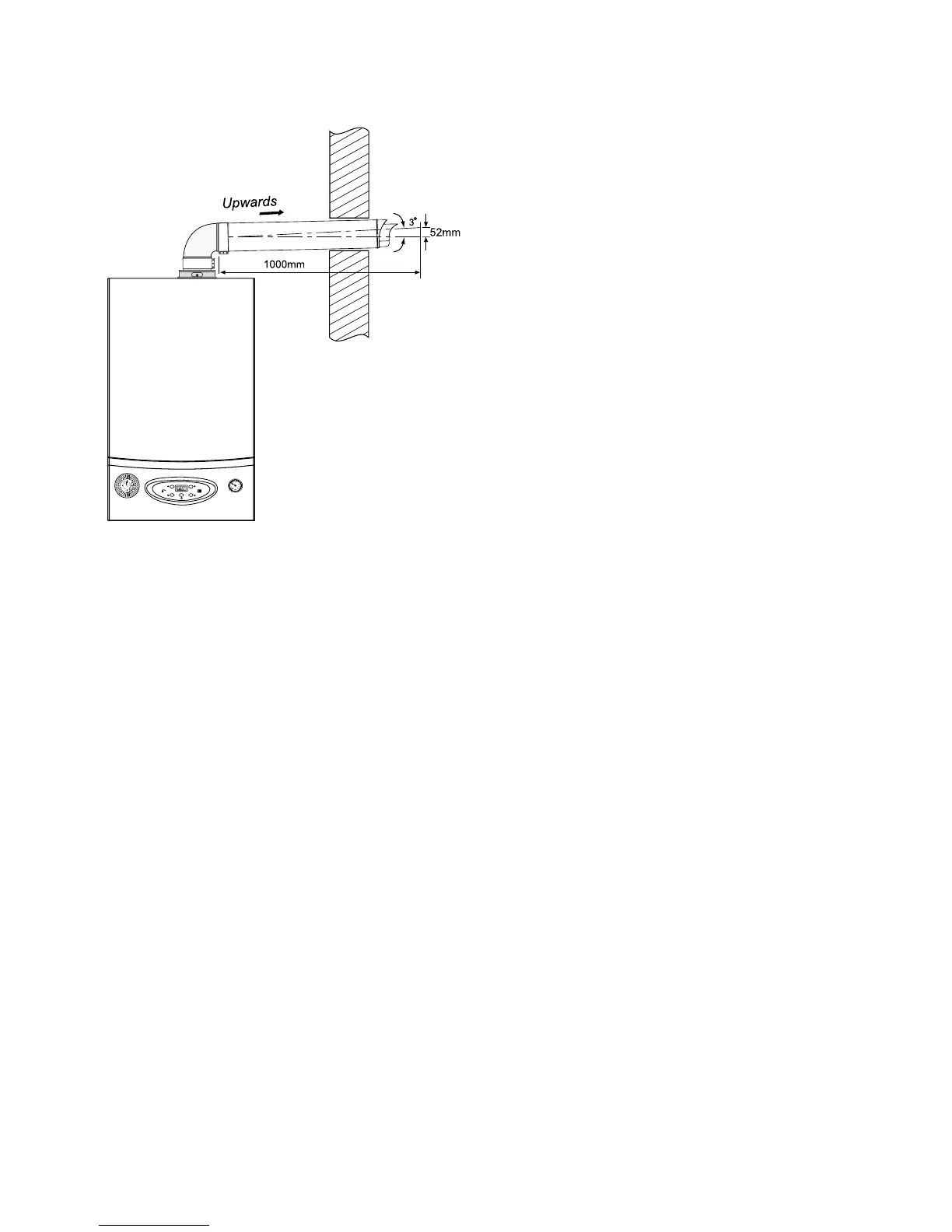
the building. Insert the 90° elbow into the top
of the boiler and rotate as required. Please
note the elbow can be rotated 360° on its
vertical axis.
Using the 30mm clamp to seal and secure the
elbow to the boiler.
Measure the required length of the flue;
measuring from the surface of the external
wall to the face of the elbow. Cut the ue duct
to the required length from the plain end,
cutting the outer ue ducting rst and then the
inner and maintaining the length between the
inner and outer ue.
Slide the internal trim ring onto the ue duct,
push the flue duct through the external wall
and attach the other end to the 90° elbow.
Using the 48mm clamp to fix the flue duct
to the elbow. Fix the internal trim ring to the
internal wall. Attach the outer wall seal to the
ue duct from the outside wall.
If the ue requires extending, the connections
are push t, but ensure each meter is secured
with a ue bracket.
Before installing the ue, ensure the maximum
length of flue ducting does not exceed 10m
for the 28Kw and 5m for the 40Kw. You
should reduce the maximum length of the ue
by 1m for each 90° elbow used and 0.5m for
each 45° elbow.
Max length for a Horizontal ue
The maximum length for a horizontal flue
is 4.0 m which includes the use of one 87°
elbow.
The maximum length is reduced by 1.0 for
each additional 87° elbow.
The Maximum length of ue is reduced by 0.5
m for each additional 45° elbow.
Max length for a Vertical ue
The maximum length for a vertical ue is 7.0
m.
The maximum length is reduced by 1.0 for
each additional 87° elbow.
The Maximum length of ue is reduced by 0.5
m for each additional 45° elbow.