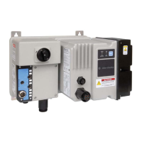
Do you have a question about the Rockwell Automation 2080-L50E-24QBB and is the answer not in the manual?
| Series | 2080 |
|---|---|
| Input Voltage | 24V DC |
| Number of Outputs | 16 |
| Digital Outputs | 16 |
| Output Type | Relay |
| Ethernet Ports | 1 |
| High-Speed Counter | Yes |
| Pulse Output | Yes |
| Product Type | Programmable Controller |
| Communication Ports | Ethernet, USB |
Defines safety labels like WARNING, ATTENTION, IMPORTANT, SHOCK, BURN, and ARC FLASH HAZARDS used in the manual.
Details the general hardware characteristics of Micro830, Micro850, and Micro870 controllers.
Describes the hardware layout and status indicators for Micro830 controllers.
Describes the hardware layout and status indicators for Micro850 controllers.
Describes the hardware layout and status indicators for Micro870 controllers.
Tables detailing input/output specifications for Micro830, Micro850, and Micro870 controllers.
Information on programming cables, embedded serial port cables, and Ethernet support.
Information on Connected Components Workbench software for programming Micro800 controllers.
Details on making changes in Run Mode using RMC and RMCC features.
Explanation of the RMC feature, its benefits, limitations, and global variable usage.
Guidance on using RMCC for changing controller address configurations over Modbus RTU and EtherNet/IP.
Using Modbus RTU and EtherNet/IP communication protocols for RMCC.
Important safety guidelines including disconnecting power, safety circuits, and power considerations.
Discussion on power supply inrush, loss of power, input states on power down, and preventing excessive heat.
Information on master control relays for emergency shutdown and using emergency-stop switches.
Details on mounting dimensions for Micro830, Micro850, and Micro870 controllers.
Instructions for DIN rail mounting and panel mounting of controllers.
Guidelines for assembling the Micro830, Micro850, and Micro870 controller systems.
Guidelines for wiring controllers, including surge suppression, grounding, and minimizing electrical noise.
Explanation and recommendations for using surge suppressors for inductive loads on AC and DC outputs.
Information on controller grounding and detailed wiring diagrams for various Micro800 controller models.
Guidance on controller I/O wiring, minimizing electrical noise, and analog channel wiring best practices.
Instructions for grounding analog cables and examples of sink/source, input/output wiring.
Details on wiring the embedded serial port, including pinouts and cable selection.
Introduction to communication connections and a list of supported protocols for Micro800 controllers.
Details on connection limits for Micro830/850/870 controllers and Modbus RTU protocol.
Information on CIP Serial (DF1), ASCII, and Modbus TCP/IP communication protocols.
Explanation of CIP symbolic addressing and messaging features for Micro800 controllers.
Details on using sockets protocol for Ethernet communication and CIP communications pass-thru.
Guidance on using modems, making DF1 connections, and configuring serial ports.
Steps for configuring Ethernet settings, validating IP addresses, and accessing diagnostics.
Introduction to DNP3 protocol, channel configuration, and slave application layer settings.
Details on Serial Port Link Layer and Ethernet Layer configuration parameters for DNP3.
Configuration parameters for the DNP3 Slave Application Layer, including driver, node address, baud, parity, and stop bits.
Steps for creating Data Set Objects using Prototypes and Descriptors in DNP3 mapping.
Methods for generating and reporting DNP3 events, including diagnostics for serial and Ethernet channels.
Techniques for collision avoidance in RS-485 networks and time synchronization for DNP3.
Introduction to Micro800 program execution, including scan cycles, POUs, and interrupts.
Explanation of program execution rules, loop duration, and handling of optional modules.
Steps for adding, configuring, updating, deleting, and monitoring motion axes in Connected Components Workbench.
Step-by-step guide to flash updating Micro800 controller firmware using Connected Components Workbench or microSD card.
Procedures for setting, changing, and clearing controller passwords using Connected Components Workbench.
Step-by-step guide on how to perform autotuning for PID controllers and troubleshooting autotune processes.


 Loading...