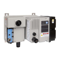
Do you have a question about the Rockwell Automation 2080-L50E-48QWB and is the answer not in the manual?
| Brand | Rockwell Automation |
|---|---|
| Model | 2080-L50E-48QWB |
| Category | Controller |
| Language | English |
Identifies practices that can cause explosions, injury, or damage.
Identifies practices that can lead to injury, property damage, or economic loss.
Identifies critical information for successful application and understanding.
Alerts to dangerous voltage presence.
Alerts to dangerous surface temperatures.
Alerts to potential Arc Flash hazards and PPE requirements.
Details the Micro830 10/16-point and 24-point controllers and their status indicators.
Details the Micro850 controllers and their status indicators.
Details the Micro870 24-point controllers and their status indicators.
Describes embedded Ethernet support, RJ-45 pin mapping, and Ethernet status indication.
Describes Connected Components Workbench software features and languages.
Explains Run Mode Change (RMC) and Run Mode Configuration Change (RMCC) features.
Details RMC benefits, ATTENTION for usage, and global variable definitions.
Lists RMC limitations and explains Run Mode Configuration Change (RMCC).
Explains RMCC for Modbus RTU and EtherNet/IP communication.
Discusses safety considerations, disconnecting main power, and explosion hazards.
Explains using emergency-stop switches and master control relay wiring.
Provides mounting dimensions for Micro830 controllers.
Describes DIN rail mounting procedures.
Describes panel mounting procedures.
Lists general wiring practices to minimize noise and ensure safety.
Explains the use of surge suppressors for inductive loads.
Covers controller I/O wiring, minimizing electrical noise, and analog channel guidelines.
Describes embedded serial port wiring, pinout explanations for RS-485 and RS-232.
Lists supported communication protocols for Micro8xx controllers.
Illustrates supported architectures for USB, EtherNet/IP, and DeviceNet connections.
Guides on configuring CIP Serial Driver with parameters and baud rate.
Guides on configuring Ethernet settings and Internet Protocol (IP) settings.
Details validating IP address, rules for IP address configuration, and DHCP server behavior.
Describes serial port link layer configuration for DNP3 slave.
Explains Ethernet layer configuration for DNP3 over IP protocol.
Explains how to add PowerFlex 520/Kinetix 5100 drives over EtherNet/IP and node count limitations.
Lists connection fault codes and their corrective actions.
Provides general rules for motion function blocks regarding parameters, inputs, and error handling.
Discusses major fault handling and defines major fault error codes for motion control.
Discusses HSC Interrupts, configuration, and shows an example of interrupt configuration.
Details workflows for working with a locked controller: Upload, Debug, and Download.
Details project backup and restore procedures using microSD cards and software.
Guides on flashing firmware using Connected Components Workbench or ControlFLASH.
Shows how to establish communications between RSLinx and Micro800 controllers via USB.
Explains how to set controller passwords using Connected Components Workbench software.
Explains how to use the High-Speed Counter, including project creation and variable assignment.
Details the Use Run Mode Change feature and how to create a project for it.
Lists error codes for Micro800 controllers, describes fault types, and recommends actions.
Compares IPIDCONTROLLER and PID function blocks, detailing common and PID-specific parameters.
Guides on how to perform autotuning for PID controllers and provides parameter recommendations.


 Loading...