Rockwell Automation Publication 2080-UM002N-EN-E - November 2022 135
Chapter 8 EtherNet/IP Network
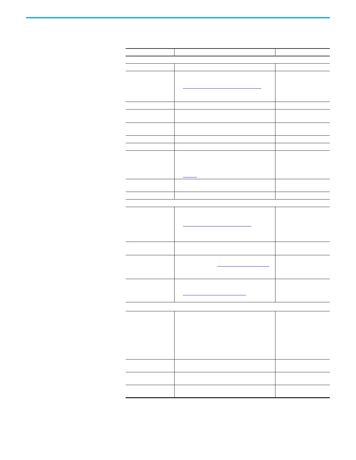
Module Properties The New Module/Configure Module window provides the properties for the module.
Table 15 - Module Properties Parameters
Parameter Description Value
General
Name Unique name of the device. User defined
Type
Select the type of profile to use with the device.
See Type Definition in Module Dialog
on page 136 for
more information.
• Generic Device
• PowerFlex 523-E2P
• PowerFlex 525-E2P
• PowerFlex 525-EENET
• Kinetix 5100
IP Address Unique IP address of the device. User defined
Mode
(1)
(1) Only displayed when PowerFlex is selected as the Type.
Define the mode of operation for the PowerFlex drive.
• Position
•Velocity
Catalog
(2)
(2) Only displayed when Kinetix is selected as the Type.
Select the right Kinetix 5100 catalog to be used.
List of Kinetix 5100 drive
catalogs (2198-Exxxx-ERS)
Major Revision Module firmware major revision. Module specific
Minor Revision Module firmware minor revision. Module specific
Electronic Keying
Software method to help reduce the possibility of using
a mismatched device in a control system.
Carefully consider the implications of each keying
option when selecting one.
See Table 16
for detailed descriptions of each option.
•Exact Match
• Compatible Module
• Disable Keying
Drive Rating
(1)
Define the PowerFlex drive rating.
List of PowerFlex drive
ratings (xP xxV xxxHP)
Description Optional description for the device. User defined
Connection
Requested Packet Interval
(RPI)
Set the RPI rate.
See Requested Packet Interval
on page 136 for more
information.
• Generic Device -
5.0…9999.9 ms
• PowerFlex Device -
5.0…9999.9 ms
• Kinetix Device -
5.0…3200.0 ms
Unicast Connection over
EtherNet/IP
Set the type of connection to use over the EtherNet/IP
network.
• Unchecked = Multicast
• Checked = Unicast
Inhibit Module
Inhibit the module. See Module Inhibiting
on page 137
for more information.
• Unchecked = Module not
inhibited
• Checked = Module
inhibited
Connection Fault
Displays the major or minor fault code when it occurs,
and can be used to help troubleshoot the module.
See Connection Fault Codes on page 147 for a list of
possible fault codes.
Fault code 0xYYYY
(for example, 0x0001)
Comm Config
(3)
(3) These parameters are displayed only when Generic Device is selected as the Type, and is used to define a generic device
data structure.
Comm Format
Defines the data structure data type in the generic
device.
• Data - DIN
• Data - INT
• Data - REAL
• Data - SINT
• Input Data - DINT
• Input Data - INT
• Input Data - REAL
• Input Data - SINT
Input
Define the Assembly Instance and size of the input
assembly in the generic device.
User defined
Output
Define the Assembly Instance and size of the output
assembly in the generic device.
User defined
Configuration
Define the Assembly Instance and size of the
configuration assembly in the generic device.
User defined
 Loading...