Rockwell Automation Publication 842E-UM002A-EN-P - November 2013 19
About the Encoder Chapter 2
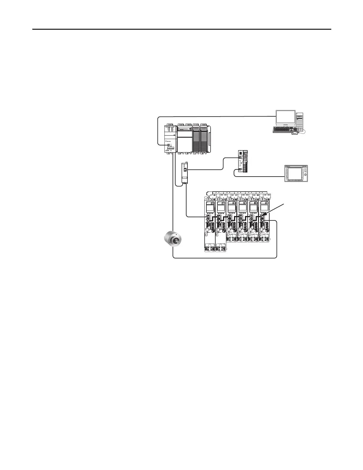
Device Level Ring Topology
A DLR network is a single-fault-tolerant ring network intended for the
interconnection of automation devices. DLR topology is advantageous as
it can tolerate a a break in the network. If a break is detected, the signals
are sent out in both directions. With this topology, use both the Link 1
and Link 2 Ethernet connections on the 842E-CM encoder.
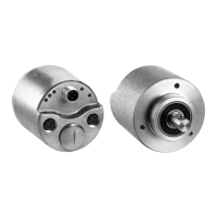
1 (Front)
2 (Rear)
1585D-M4TBJM-x
Ethernet (shielded) cable
1734-AENTR POINT I/O
EtherNet/IP adapter
CompactLogix controller programming network
1783-ETAP
module
1585J-M8CBJM-OM3
0.3 m (1.0 ft) Ethernet cable
for drive-to-drive connections.
PanelView Plus
display terminal
Kinetix 5500 servo drive system
CompactLogix 5370 controller
Logix Designer
application
842E-CM encoder
 Loading...