24 Rockwell Automation Publication 842E-UM002A-EN-P - November 2013
Chapter 3 Installation
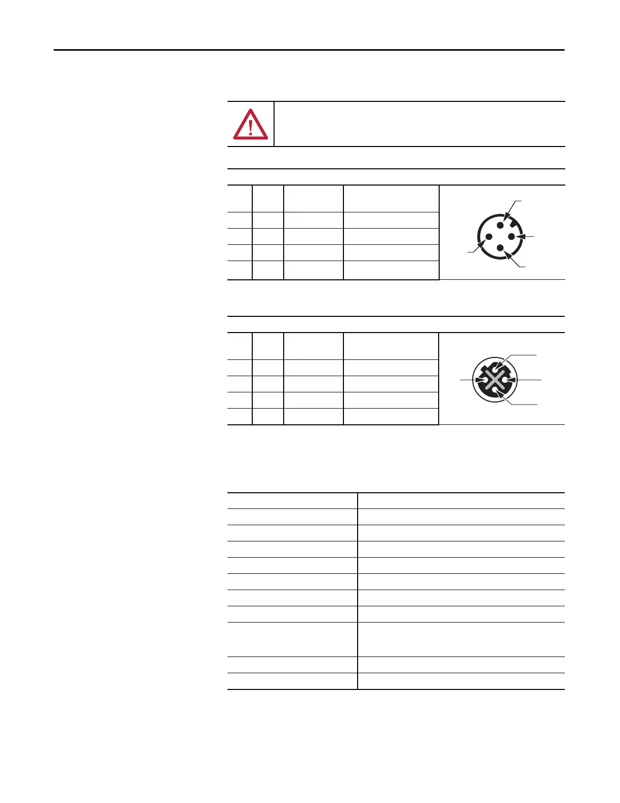
Pin Assignments
Functional Specifications
ATTENTION: Wire the voltage supply as shown. Mis-wiring can cause damage
to the encoder.
Voltage supply
Signal Mating cable
wire color
Function
1 Vs Brown Supply voltage 10…30V DC
2WhiteDo not use
3 GND Blue 0V DC (ground)
4BlackDo not use
Example: Cordset 889D-F4AC-*
Ethernet link connections – Link 1 and Link 2
Pin Signal Mating cable
wire color
Function
1 TxD+ White orange Ethernet
2 RxD+ White green Ethernet
3 TxD– Orange Ethernet
4 RxD– Green Ethernet
Example: Cordset 1585D-M4TBJM-*
Operating voltage 10…30V DC
Power consumption 3 W
Load current 200 mA
Resolution per revolution 262,144
Revolutions 4,096
Repeat accuracy ±0.002°
Error limit ±0.03°
Code direction CW or CCW programmable
Interface EtherNet/IP per IEC 61784-1
IEEE 1588 (IEEE 61588, Precision clock synchronization protocol for
networked measurement and control systems)
Transmission speed 100 MBits/s
Duplex Full or half
1-Brown
V
s
4
Blue - 3
GND
2
1
4
3
2
 Loading...