10 1769-L32E, 1769-L35E CompactLogix Controller
Publication
1769-IN020D-EN-P - October 2008
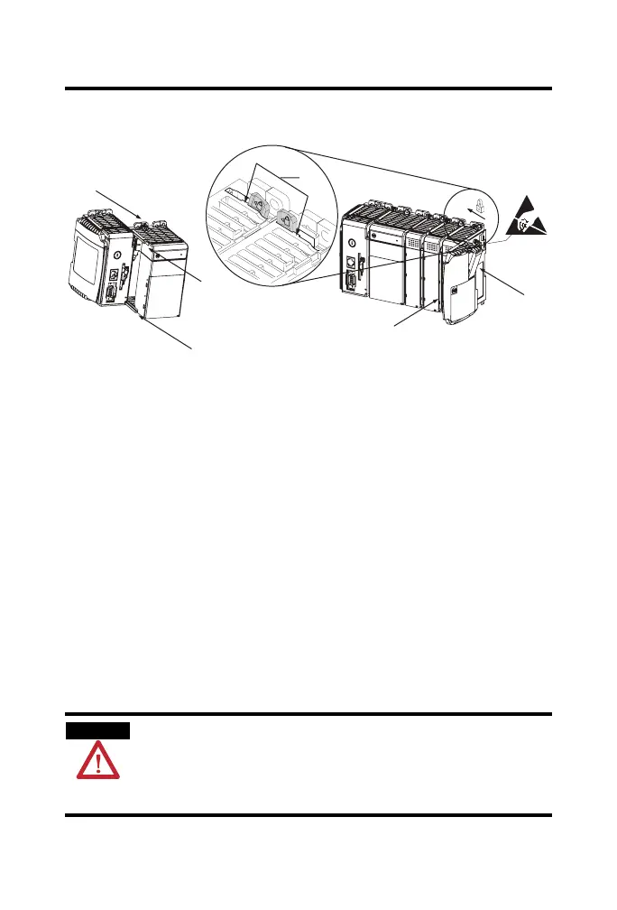
Refer to the illustration when installing a controller.
1. Disconnect line power.
2. Check that the lever of the adjacent module (A) is in the unlocked
(fully right) position.
3. Use the upper and lower tongue-and-groove slots (B) to secure the
modules together.
4. Move the module back along the tongue-and-groove slots until the
bus connectors line up with each other.
5. Use your fingers or a small screwdriver to push the module’s bus lever
back slightly to clear the positioning tab (C).
6. Move the module’s bus lever fully to the left (D) until it clicks, being
sure it is locked firmly in place.
ATTENTION
When attaching the controller, power supply, and I/O modules, make sure the
bus connectors are securely locked together to be sure of proper electrical
connection.
This equipment is not resistant to sunlight or other sources of UV radiation.
A
B
B
C
D
E
F
44733

 Loading...


