16 Rockwell Automation Publication 440G-UM001C-EN-P - June 2019
Chapter 3 Installation
Allowable Approach
Directions
The actuator can approach the switch from all four directions.
Verify that the white arrow on the actuator aligns with the white arrow on the
switch body.
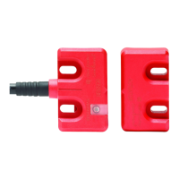
Mounting the Switch Body
Three M5 fasteners (not provided) are required for proper mounting to a rigid
guard door frame.
IMPORTANT Washers are not required and if used can cause the mounting holes on the
switch body to crack.
If it is decided to use a standard thread-locking compound on the mounting
screws of the switch body, check the manufacturer’s specification. Many
standard thread-locking compounds can attack the plastic feet of the switch
body, which can cause stress cracks. It is recommended to use
cyanoacrylate-type thread-locking compounds.
 Loading...