Rockwell Automation Publication 440G-UM001C-EN-P - June 2019 21
Chapter 4
Wiring
Connections
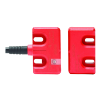
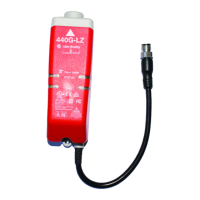
The 440G-LZ safety switch is available with an 8-pin DC Micro M12 quick-
disconnect connector. Figure 8
and Tabl e 5 show the pin assignments and their
functions and typical mating cordsets. Other cordsets are available at DC
Micro Cordsets and Patchcords.
Figure 8 - 8-pin Micro Quick Disconnect Cables
Table 5 - 440G-LZ Safety Switch Quick Disconnect Pin Assignments
1
Replace symbol with 2 [2 m (6.56 ft)], 5 [5 m (16.4 ft)], 10 [10 m (32.8 ft)], 15 [15 m (49.2 ft)] 20 [20 m [65.62 ft)] or 30 [30 m
(98.4ft)] for standard cable lengths. The 440G-LZ safety switch has been tested to operate with up to 120 m (393.7 ft) of the
mating cables.
OSSD Inputs
The OSSD inputs are Safety A+ and Safety B+. These inputs are 24VDC
signals, which can contain test pulses. The OSSD inputs allow the 440G-LZ
safety switches to be connected in series while maintaining a high level of safety
performance.
OSSD Outputs
The OSSD outputs are Safety A and Safety B. These outputs are 24V signals
that contain test pulses. The test pulses are used to detect short circuits to 24V,
to 0V and cross faults (from Safety A to Safety B). This description of the test
pulses is provided for informational purposes; you cannot modify them.
Typical Mating Cordsets Color Function Pin
889D-F8NB-x
1
(Red, PVC)
889D-F8AB-x
1
(Black, PVC)
White Aux 1
Brown 24V DC Supply 2
Green Lock Command 3
Yellow Safety B+ Input 4
Gray Safety A Output (OSSD A) 5
Pink Safety B Output (OSSD B) 6
Blue Ground (0V) 7
Red Safety A+ Input 8
2 24V DC+
1 Aux
7 0V
6 Safety B Output
3 Lock Command
8 Safety A+ Input
4 Safety B+ Input
5 Safety A Output
 Loading...