44 Rockwell Automation Publication 440G-UM001C-EN-P - June 2019
Chapter 7 Application Examples
Figure 16 - CR30 Configuration in CCW
Wiring to 1734
Guard Point I/O
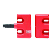
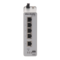
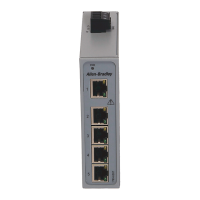
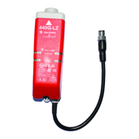
The 440G-LZ safety switch can be connected to a 1734 Guard Point I/O. The
cordset (catalog number 889D-F8NB) has 24 AWG wires, which allows three
wires to be connected to one terminal.
Figure 17 on page 44
shows a wiring example of a Power-to-Lock switch with a
Door Status auxiliary signal. The PLC logic checks to see if the door is closed
before issuing a lock command. The schematic for this example is shown in
Figure 22 on page 47
.
Figure 17 - 1734 and 440G-LZ Safety Switch Schematic
1734-IB8S1734-AENT 1734-OB8S
24V DC Com
I0
I1
I2
T0
I3
T1M
COM COM
I4
I5
I6
T2
I7
T3M
COM COM
0
1
2
6
3
7
45
O0
O1
O2 O3
COM COM
O4
O5
O6 O7
COM COM
COM COM COM COM
+24V DC
K1
K2
Ethernet I/P
to GuardLogix
PLC and HMI
Red (OSSD A+)
Pink (OSSD B)
Green (Lock)
White (Aux)
Blue (0V)
Grey (OSSD A)
Yellow (OSSD B+)
Brown (+24V)
Safety
Gate
440G-LZS21STLH
Power-to-Lock
Aux = Gate Status
889D-F8NB-10
K2
Diag
Status
440G-LZ
K1
 Loading...