Rockwell Automation Publication 440G-UM001C-EN-P - June 2019 17
Installation Chapter 3
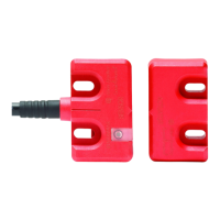
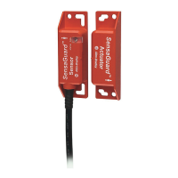
Actuator Alignment
There are three ways to achieve proper alignment.
1. By setting gap
“G”
2.5 mm (0.09 in.)
[
0…5 mm (0…0.19 in.)
]
2. By mounting hole alignment
“H”
6.5 mm
(0.25 in.) [4…9 mm (0.15…0.35 in.)]
3. Use the alignment
guide
provided
ATTENTION: After installation, verify that
there is no possibility of lifting the actuator
over the extended locking bolt.
ATTENTION: After installation, confirm that
there is no possibility of collision when the
actuator approaches the switch body.
 Loading...