Rockwell Automation Publication 440G-UM001C-EN-P - June 2019 53
Appendix A
Specifications and Safety Ratings
Introduction
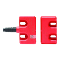
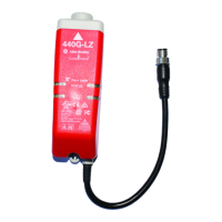
This appendix provides the specifications and safety ratings for the
Guardmaster® 440G-LZ guard locking safety switch.
Table 15 - Operating Characteristics
Attribute Value
Switch function OSSDs enable when guard closed and locked
Torque for M5 mounting of switch and actuator
mounting bracket
2 N•m (17.7 lb•in) max
Lock bolt insertion for assured lock and hold force 5 mm (0.19 in.) min, 10 mm (0.39in.) max
Approach speed 2 mm/s, min
Lock bolt alignment tolerance X, Y, Z ± 2.5 mm (0.1 in.), max
Hold force F
max
(ENISO14119) 1,690 N
Hold force F
zh
(ENISO14119)
(1)
(1) The holding force F
zh
is in accordance to ENISO14119:2013, clause 5.7.4. Additional validation was performed in accordance
with IEC 60947-5-1:2009, clause C.1.2.2.
1,300 N
Maximum output current (each output) 200 mA
Quiescent power consumption, locked or unlocked 2.5 W
Lock signal current 3.5 mA signal on green lock/unlock wire
Peak current, during turn-on or after Lock/Unlock
operation
400 mA
Duration of peak current, at turn-on or after Lock/Unlock
operation
100 ms
Number of switches connectable in series Unlimited, see Response Time When Connected in Series
Circuit on page 25
Operating voltage U
e
24V DC + 10%/-15% Class 2 SELV
Frequency of operating cycles 0.2 Hz, max
Dwell time between subsequent locking/unlocking 2.5 s
Response time (Off) 100 ms first switch, +50 ms for each additional switch
Risk time 100 ms (according to IEC 60947-5-3)
Start-up time 5 s (availability)
Usage category DC-13 24V 200 mA, (IEC 60947-5-2)
Insulation voltage U
i
(IEC 60947-5-1) 75V
Impulse withstand voltage U
imp
(IEC 60947-5-1) 1 kV
Pollution degree (IEC 60947-5-1) 3
Manual (auxiliary) release Built-in
Emergency release No
Escape release No
Protection class (IEC 61140) Class II
Mechanical life 500,000 cyles
 Loading...