Rockwell Automation Publication 440G-UM001C-EN-P - June 2019 41
Application Examples Chapter 7
Circuit Status as Shown
The E-stop is released. The gate is open and unlocked. K1, K2, K3, and K4 are
OFF. The DI is configured for two inputs with monitored manual reset. The
EMD is configured for 8-second off-delay; Range setting of 2 is 10 s, Time
setting of 8 is 80% of the range. The X32 terminal is ON because the EMD
safety outputs are OFF.
Starting
With the Unlock switch open, close the gate. Press Reset to lock the gate and
turn on the K1…K4 safety contactors.
Stopping
Stopping is initiated by pressing the E-stop. K1 and K2 contactors turn off
immediately. The single wire safety signal from the DI (L11) to the EMD
(L12) also turns off immediately, and the EMD starts the off-delay timer. After
8 seconds, contactors K3 and K4 turn OFF and X32 goes to 24V. The unlock
switch is enabled, and the gate can be unlocked. While the gate is unlocked, the
DI cannot turn the safety outputs back ON. After you leave the cell and close
the gate, open the unlock switch to lock the gate, and release the E-stop.
The circuit can meet the safety requirements up to Category 4, Performance
Level e in accordance with ISO 13849-1 and SIL CL 3 in accordance with
IEC62061.
Wiring to DG Relay
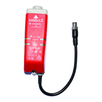
The 440G-LZ safety switch can be used in GuardLink® applications. The
GuardLink system:
• Is designed to operate with Power to Release switches,
• Uses taps to connect a series of devices to one relay,
• Provides control and status information between the machine control
system and the safety system.
Figure 14 on page 42
shows four 440G-LZ safety switches that are connected
on two GuardLink circuits from one DG relay. The DG relay can
accommodate up to 32 devices on each input. The devices can be a mix of
many different safety devices. When guard locking devices are included in the
GuardLink system, the lock/unlock command must come from the machine
control system through the 440R-ENETR module.
See publication 440R-UM015
for further details.

 Loading...