40 Rockwell Automation Publication 440G-UM001C-EN-P - June 2019
Chapter 7 Application Examples
and close the gate, press Reset to lock the gate and return the machine to a
production state.
The circuit meets the safety requirements up to Category 3, Performance
Leveld in accordance with ISO 13849-1 and SIL CL 2 in accordance with
IEC 62061.
Wiring to DI and EMD Relay
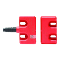
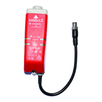
The 440G-LZ safety switch can be connected to the DI and EMD safety
relays. The DI monitors the safety outputs of the safety switch and the EMD
enables the gate to be unlocked after a configured delay time expires.
B1 is connected to B2 to allow for retriggering. If you open and close the
E-stop and press Reset before the delay expires, the EMD timer resets.
Upon initial power-up, the safety switch must be cycled for the DI to recognize
the safety switch OSSD signals.
In the example shown in Figure 13
, an E-stop initiates the machine shutdown.
After an eight-second delay, the safety switch is allowed to be unlocked and the
hazards that remain are turned OFF. A selector switch is required to maintain
the gate in an unlock state. The risk assessment must determine adequate time
delay for the machine to achieve a safe state before unlocking the gate.
Figure 13 - DI with EMD and 440G-LZ Safety Switch Schematic
889D-F8AX-X
Pigtail
deR
nrB
Wht
Grn
Pnk
Gry
leY
Blu
Power
In 1
In 2
Out
Logic
A2
A1
+-
S1 1
S2 1
S1 2
S22
S3 2
S4 2
L12
L11
Y3 2
S3 4
13
14
23
24
24V DC
IN1
DI
IN 2
0
1
2
3
4
56
7
8
LOGIC
Test Out
A2
A1
+-
B2
37
B1
47
48
38
L12
L11
X32
17
27
28
18
24V DC
EMD
17
18
27
28
37
38
47
48
N/C
E-Stop
K1
K2
M
K1
K2
Reset
440G-LZS
24V DC Supply
24V DC COM
Unlock
 Loading...