Rockwell Automation Publication 442G-UM002B-EN-P - August 2021 47
Appendix C
Change Actuation Direction of Handle Assembly
Procedure If a right-hand assembly must be mounted on a left-hinged guard door or a
left-hand assembly must be mounted on a right-hinged guard door, the
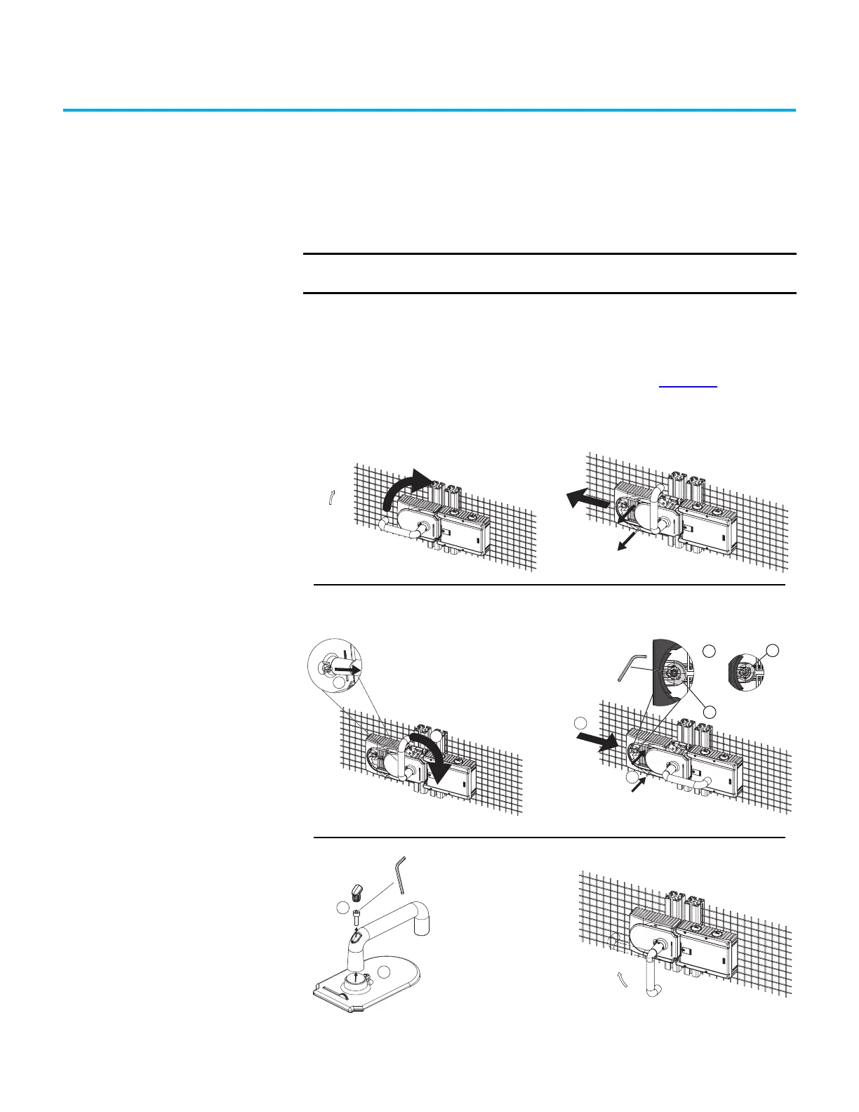
actuating direction of the door handle must be changed. Figure 23
shows the
process to change from right- to left-hand operation.
Figure 23 - Change Actuation Direction
IMPORTANT It is only possible to perform this change when the bolt is not extended
and an escape release is not yet mounted.
1 - Press door handle up.
2 - Unscrew mounting screws
on handle assembly.
CLOSED
OPEN
3 - Push cover aside.
4 - Lift the Locking pin on the door handle with a
screwdriver and hold it in this position.
6 - For escape release only: With the hexagon head
screw, turn the joint counterclockwise from position (a)
to position (b).
5 - Turn the door handle
to the right.
7 - Close cover.
8 - Screw in the mounting
screws and tighten to 2 N•m
(17.7 lb•in).
3 mm
9
10
10 - Reposition the door handle by
90° in clockwise direction and fasten
it again. Tighten setscrew to 2 N•m
(17.7 lb•in).
9 - Loosen the
setscrew.
Final state after repositioning.
 Loading...