Program a Function Block Diagram
16 Rockwell Automation Publication 1756-PM009G-EN-P - February 2018
within a specific group execute in the appropriate order in relation to the
blocks in that group.
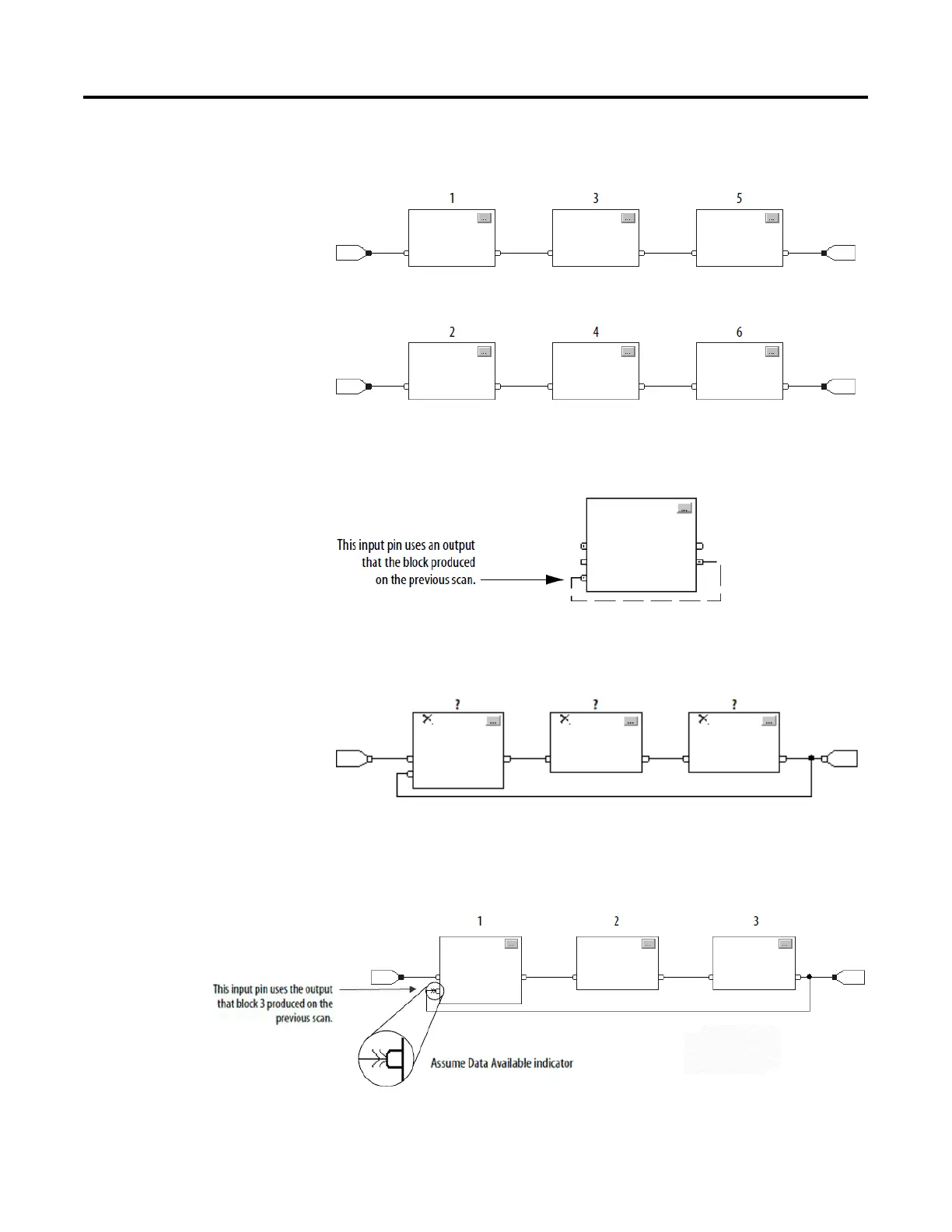
To create a feedback loop around a block, wire an output pin of the block to
an input pin of the same block. In this example, the loop contains only a
single block, so execution order does not matter.
If a group of blocks are in a loop, the controller cannot determine which
block to execute first, and it cannot resolve the loop, as illustrated in this
example.
To identify which block to execute first, mark the input wire that creates the
loop (the feedback wire) with the Assume Data Available indicator. In this
example, block 1 uses the output from block 3 that was produced in the
previous execution of the routine.
The Assume Data Available indicator defines the data flow within the loop.
The arrow indicates that the data serves as input to the first block in the loop.
 Loading...


