EasyManua.ls Logo

Rockwell Automation Allen-Bradley Logix 5000 User Manual

Rockwell Automation Allen-Bradley Logix 5000
33 pages
To Next Page IconTo Next Page
To Previous Page IconTo Previous Page
Page #13 background imageLoading...
Page #13 background image
Program a Function Block Diagram
Chapter 1
Rockwell Automation Publication 1756-PM009G-EN-P - February 2018 13
For a: Specify:
Element of a two dimension array
tag_name[x,y]
Element of a three dimension array
tag_name[x,y,z]
Element of an array within a structure
tag_name.member_name[x]
Member of an element of an array
tag_name[x,y,z].member_name
where:
x is the location of the element in the first dimension.
y is the location of the element in the second dimension.
z is the location of the element in the third dimension.
For a structure within a structure, add an additional member_name.
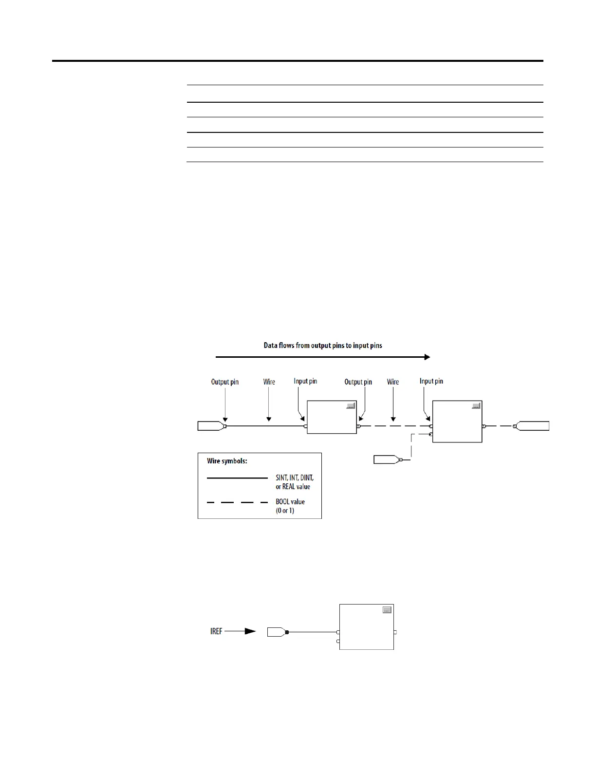
Define execution order (flow of data) by wiring elements together and
indicating any input (feedback) wires, if necessary. The location of a block
does not affect the order in which the blocks execute.
If you use an IREF to specify input data for a function block instruction, the
data in that IREF is latched for the scan of the function block routine. The
IREF latches data from program-scoped and controller-scoped tags. The
controller updates all IREF data at the beginning of each scan as shown in
this diagram.
In this example, the value of tagA is stored at the beginning of the execution
of the routine. The stored value is used when Block_01 executes. The same
stored value is also used when Block_02 executes. If the value of tagA
Define the order of
execution
Data latching
Question and Answer IconNeed help?

Do you have a question about the Rockwell Automation Allen-Bradley Logix 5000 and is the answer not in the manual?

Rockwell Automation Allen-Bradley Logix 5000 Specifications

General IconGeneral
BrandRockwell Automation
ModelAllen-Bradley Logix 5000
CategoryController
LanguageEnglish

Summary

Important User Information

Safety Warnings and Precautions

Details critical safety warnings including explosion, injury, and electrical hazards.

Summary of Changes

Global Changes Overview

Identifies changes applicable across the manual.

New Features Summary

Lists recently added or enhanced features.

Preface

Studio 5000 Environment Introduction

Introduces the Studio 5000 Automation Engineering & Design Environment.

Additional Resources and Legal Information

Provides links to related documents, legal terms, and software notices.

Warranty and Contact Information

Covers product warranty, environmental compliance, and support contact details.

Chapter 1: Program a Function Block Diagram

Routine Organization with Sheets

Explains organizing routines with sheets for navigation.

Function Block Elements

Details the elements used to control devices in FBD, like IREF, OREF, ICON, OCON.

Tag Naming Conventions

Guides on creating and assigning tag names for function block elements.

Defining Execution Order

Explains how to define the sequence of block execution via wiring.

Data Latching with IREFs

Describes how IREFs latch data for function block scans.

Determining Execution Order

Explains how the Logix Designer application determines block execution sequence.

Resolving Feedback Loops

Illustrates how to resolve feedback loops in function block diagrams.

Resolving Data Flow Between Blocks

Provides guidance on data flow indicators for multiple wires connecting blocks.

Creating a One Scan Delay

Shows how to implement a one scan delay using the Assume Data Available indicator.

Using Connectors (OCON/ICON)

Explains the purpose and rules for using output and input connectors.

Program and Operator Control

Details how to manage instruction control between program and operator interfaces.

Adding a New Sheet

Step-by-step guide to add a new sheet to a function block routine.

Adding Function Block Elements

Instructions on adding various elements like IREF, OREF, etc., from the toolbar.

Creating Text Boxes for Notes

Explains adding text boxes for clarifying FBD elements.

Managing Language Switching

Discusses options for supporting and switching project documentation languages.

Showing and Hiding Pins

Details how to show or hide pins in function block properties.

Wiring Elements Together

Guides on connecting elements by wiring output to input pins.

Marking Wires with Assume Data Available

Explains marking feedback wires to define loop data flow.

Creating and Assigning New Tags

Step-by-step guide to create and assign a new tag to an element.

Assigning Existing Tags

Instructions for assigning an existing tag from the Tag Browser.

Assigning Immediate Values (Constants)

Explains how to assign constant values directly to parameters.

Using IREFs for Value Assignment

Details the process of assigning values to IREFs.

Entering Values in Block Tags

Describes entering values directly into block tags via wire connections.

Adding Output and Input Connectors (OCON/ICON)

Guides on adding and configuring OCON and ICON elements.

Renaming Wire Connectors

Explains how to rename ICON or OCON elements individually.

Renaming Connector Groups

Describes how to rename multiple connected elements simultaneously.

Verifying Function Block Routines

Guides on using the Verify function to check for errors in routines.

Rockwell Automation Support

Installation Assistance and Returns

Provides support for product installation and return procedures.

Documentation Feedback

Instructions for submitting feedback on the manual.

Related product manuals