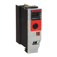
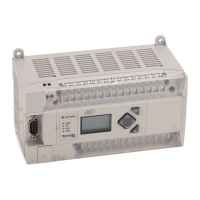
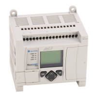
Do you have a question about the Rockwell Automation Logix 5000 and is the answer not in the manual?
Summarizes critical safety warnings and hazard identifications for user protection.
Lists changes that apply to the entire document release.
Details specific new functionalities or improvements introduced in this version.
Describes the Studio 5000 Automation Engineering & Design Environment and its components.
Lists supplementary documents and online resources for further information.
Covers End User License Agreement (EULA) and open source software license information.
Explains the purpose of function block routines and the use of sheets for organization.
Details the different elements used in function block diagrams and their purpose.
Explains how to assign tags to function block elements for configuration and status.
Describes how to define the sequence of operation for function blocks using wiring.
Explains how input reference (IREF) data is latched for function block execution scans.
Details how to create and manage feedback loops within function block diagrams.
Explains how to correctly manage data flow indicators for connections between blocks.
Shows how to use the Assume Data Available indicator to create a one-scan delay.
Explains the purpose and usage rules for connectors in function block diagrams.
Describes how instructions can be controlled by either the program or an operator interface.
Provides steps to add a new sheet to a function block routine for better organization.
Guides on how to add function block elements from the Language Element toolbar.
Explains the use of functions for mathematical, comparison, and logical operations in FBDs.
Details how to add descriptive text boxes to clarify FBD elements.
Covers the capability to display project documentation in multiple languages.
Explains how to manage the visibility of pins on function block elements.
Describes the process of connecting output pins to input pins of function block elements.
Explains how to use the Assume Data Available indicator for feedback wires in loops.
Guides on creating a new tag within the Logix Designer application.
Details how to assign a pre-existing tag to a function block element.
Describes how to assign constant values directly to input parameters.
Explains how to use an Input Reference (IREF) to assign a value to a parameter.
Shows how to input a value directly into a block's parameter without wiring.
Introduces Output Wire Connector (OCON) and Input Wire Connector (ICON) for data transfer.
Step-by-step guide to adding and naming an Output Wire Connector (OCON).
Step-by-step guide to adding and naming an Input Wire Connector (ICON).
How to edit the name of individual wire connectors (ICON or OCON).
How to rename multiple wire connectors that share a name.
Instructions on how to check for errors and warnings in a programmed routine.
Information on how to provide feedback for improving documentation.
Guidance on the proper disposal of electronic equipment at its end of life.
| I/O Support | Digital, Analog, Specialty I/O |
|---|---|
| Communication Protocols | EtherNet/IP, ControlNet, DeviceNet, Serial |
| Programming Languages | Ladder Logic, Structured Text, Function Block Diagram, Sequential Function Chart |
| Programming Software | Rockwell Automation Studio 5000 Logix Designer |
| Operating Temperature | 0°C to +60°C |
| Power Supply | Varies by model (e.g., 24V DC, 120/240V AC) |
| Certifications | UL, CE, ATEX |


 Loading...