Chapter 1 Program a Function Block Diagram
Rockwell Automation Publication 1756-PM009J-EN-P - March 2022 17
The
indicator defines the data flow within the loop.
The controller cannot resolve the loop because all the wires use the
indicator.
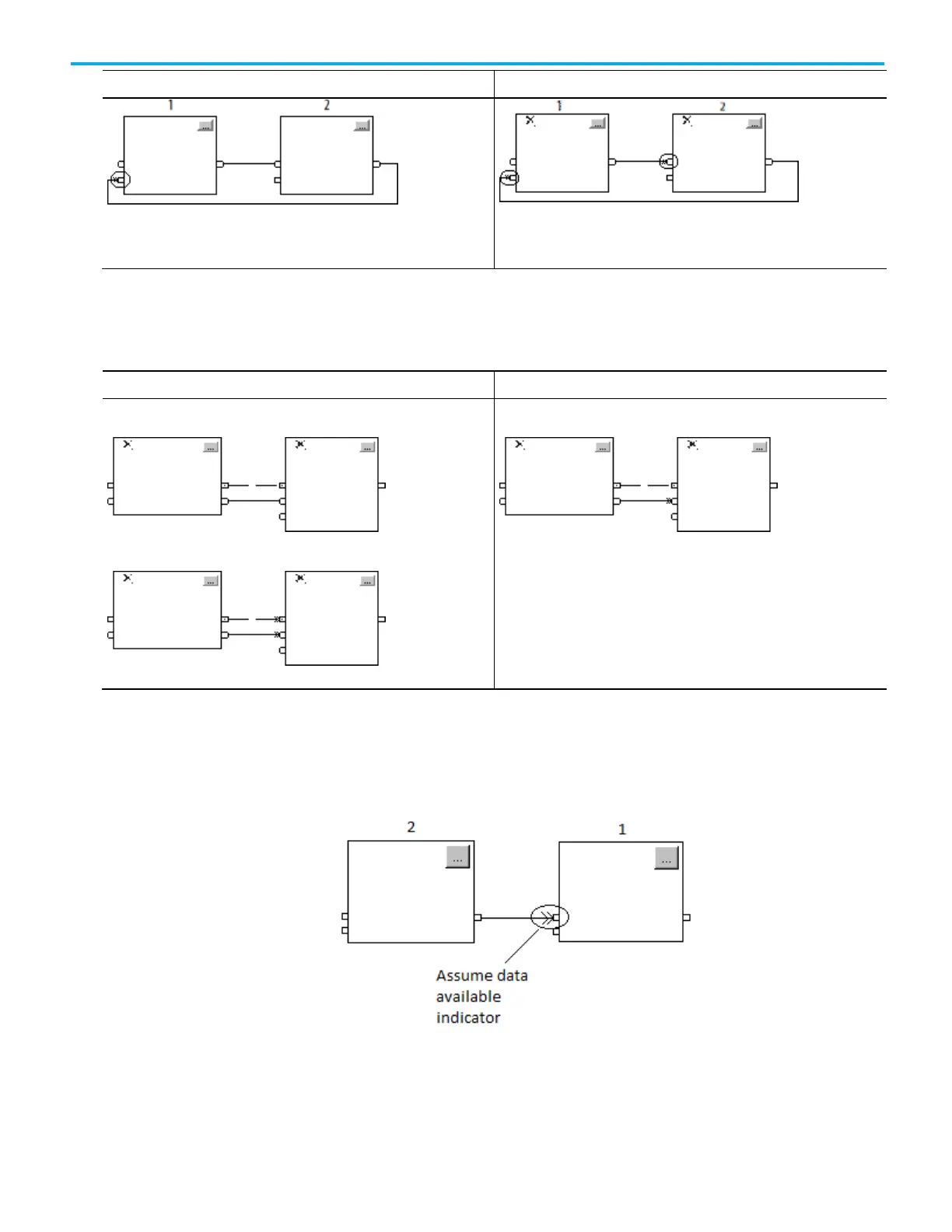
When using two or more wires to connect two blocks, use the same data flow
indicators for all of the wires between the two blocks.
In this example, neither wire uses the Assume Data Available indicator.
In this example, both wires use the
indicator.
In this example, only one wire uses the Assume Data Available indicator.
Use the Assume Data Available indicator to produce a one scan delay between
blocks. In this example, block 1 executes first. It uses the output from block 2
that was produced in the previous scan of the routine.
Resolve data flow between
two blocks
 Loading...


