Chapter 1 Program a Function Block Diagram
Rockwell Automation Publication 1756-PM009J-EN-P - March 2022 25
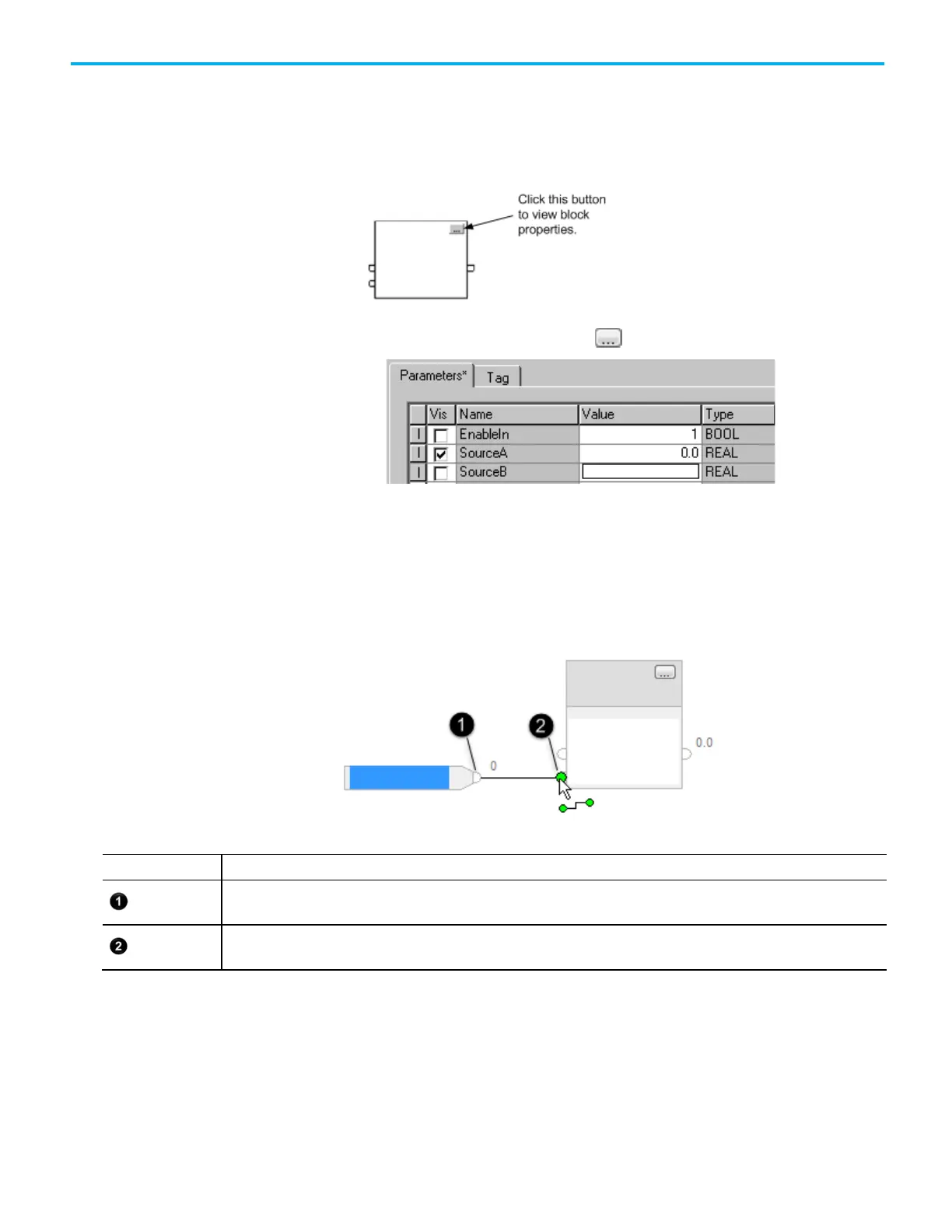
Function Block instructions provide a set of pins for the default parameters.
The rest of the pins are hidden. Show or hide a pin on the Parameters tab in
the Properties dialog box.
1. In the block, click Properties .
2. In the Properties dialog box, on the Parameters tab, clear the Vis
check box to hide the pin. Select the Vis check box to show the pin.
3. Click OK.
Wire (connect) two elements together by clicking the output pin of the first
element and clicking the input pin of the other element. A green dot shows a
valid connection point.
Output pin of the first element
Input pin of the second element
When there are a group of blocks in a loop, identify which block executes first.
The Assume Data Available indicator marks the input wire that creates the
loop (the feedback wire). It defines the data flow within the loop.
• To define a wire as an input wire, right-click the wire and click Assume
Data Available.
Show or hide a pin
Assume Data Available
indicator
 Loading...


