Chapter 1 Program a Function Block Diagram
18 Rockwell Automation Publication 1756-PM009J-EN-P - March 2022
A function block routine executes in this order.
1. The controller latches all data values in IREFs.
2. The controller executes the other function blocks in the order
determined by how they are wired.
3. The controller writes outputs in OREFs.
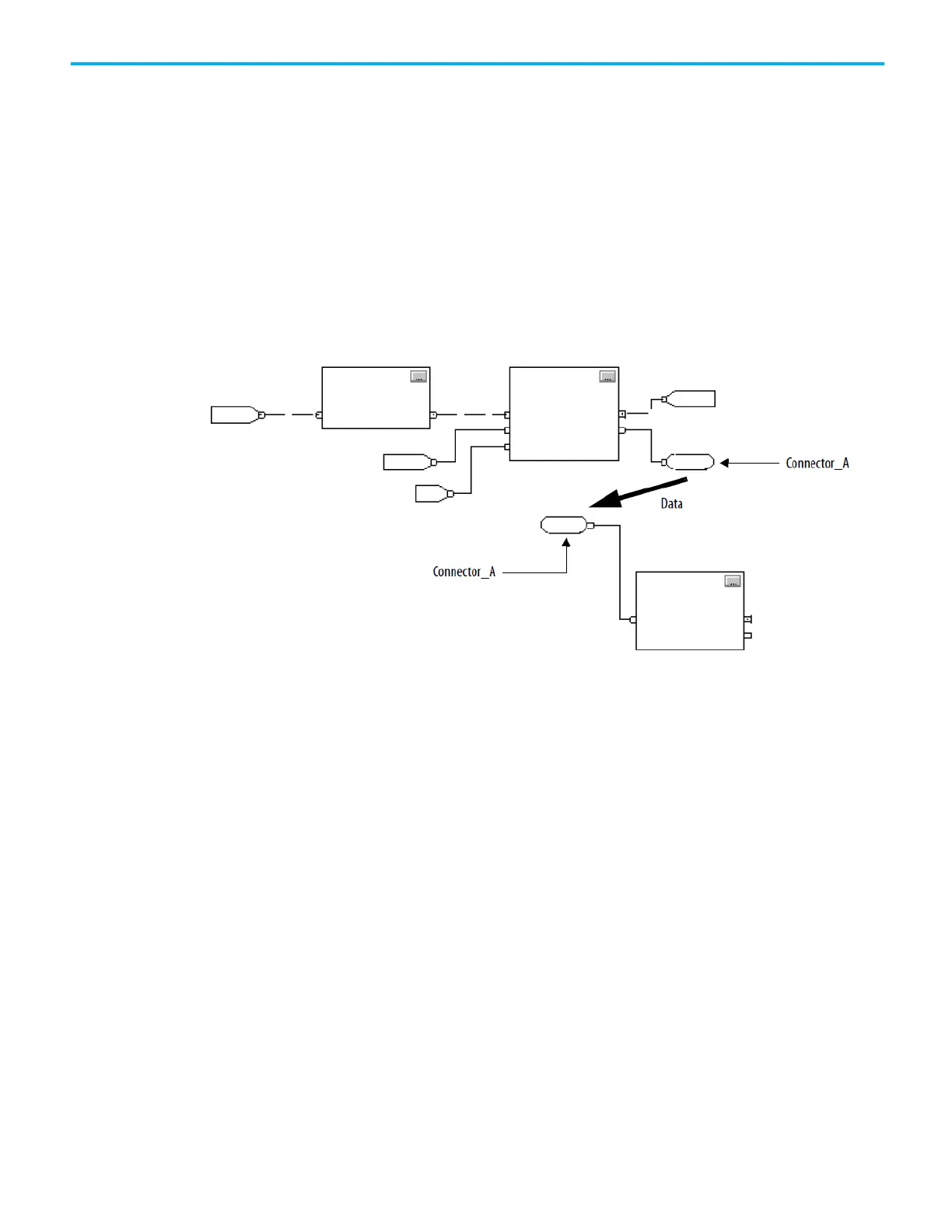
Like wires, connectors transfer data from output pins to input pins. Use
connectors when:
• The elements to connect are on different sheets within the same
routine.
• A wire is difficult to route around other wires or elements.
• Data should be dispersed to several points in the routine.
To use connectors, use these rules.
• Each OCON requires a unique name.
• Each OCON must have at least one corresponding ICON, such as an
ICON with the same name as the OCON.
• Multiple ICONs can reference the same OCON. This allows dispersal of
data to several points in a routine.
These instructions support the concept of Program/Operator control.
• Enhanced Select (ESEL)
• Totalizer (TOT)
• Enhanced PID (PIDE)
• Ramp/Soak (RMPS)
• Discrete 2-State Device (D2SD)
• Discrete 3-State Device (D3SD)
Program/Operator control allows simultaneous control of these instructions
from the user program and from an operator interface device. When in
Program control, the instruction is controlled by the Program inputs to the
instruction. When in Operator control, the instruction is controlled by the
Operator inputs to the instruction.
Program or Operator control is determined by using these inputs:
control
 Loading...


