EasyManuals Logo

Rockwell Automation Allen-Bradley Logix 5000 User Manual

Rockwell Automation Allen-Bradley Logix 5000
33 pages
To Next Page IconTo Next Page
To Previous Page IconTo Previous Page
Page #17 background imageLoading...
Page #17 background image
Program a Function Block Diagram
Chapter 1
Rockwell Automation Publication 1756-PM009G-EN-P - February 2018 17
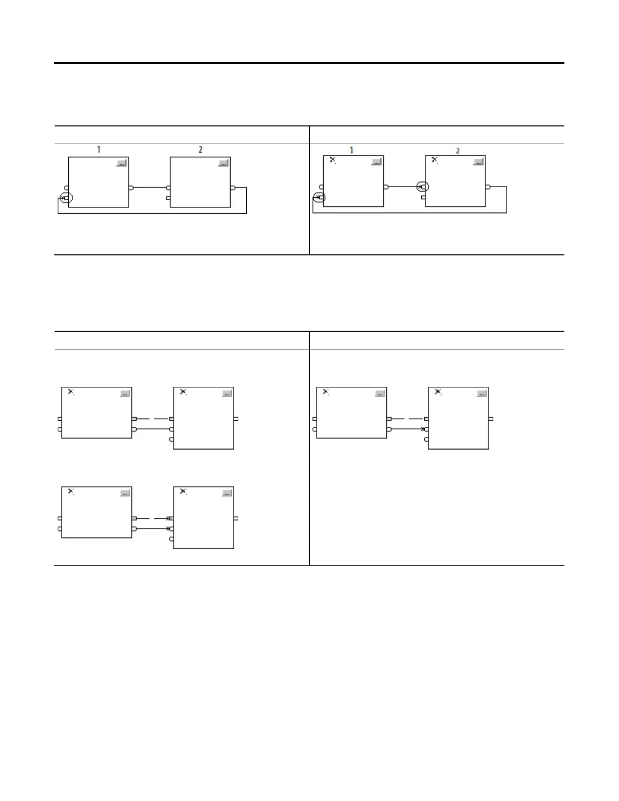
Do not mark all the wires of a loop with the Assume Data Available
indicator.
This example is OK.
This example is not OK.
The Assume Data Available indicator defines the data flow
within the loop.
The controller cannot resolve the loop because all the wires
use the Assume Data Available indicator.
If you use two or more wires to connect two blocks, use the same data flow
indicators for all of the wires between the two blocks.
This is OK
This is NOT OK
In this example, neither wire uses the Assume Data
Available indicator.
In this example, both wires use the Assume Data Available
indicator.
In this example, only one wire uses the Assume Data
Available indicator.
Resolve data flow
between two blocks

Questions and Answers:

Question and Answer IconNeed help?

Do you have a question about the Rockwell Automation Allen-Bradley Logix 5000 and is the answer not in the manual?

Rockwell Automation Allen-Bradley Logix 5000 Specifications

General IconGeneral
BrandRockwell Automation
ModelAllen-Bradley Logix 5000
CategoryController
LanguageEnglish

Related product manuals