Rockwell Automation Publication 20P-TD001K-EN-P - January 2021 17
PowerFlex DC Drive and Field Controller Technical Data
Install an SCR Overvoltage Protection Device
When the PowerFlex DC field controller is used as a motor/generator field supply, an overvoltage protection device (voltage clamp) must be
installed on the field controller load. The purpose of the voltage clamp is to provide a means to let the DC output current to the load decay if
the power is interrupted to the field controller. If the AC power to the connected field controller is interrupted, the current in the DC output to
the field starts to the decay rapidly. This rapid decay generates voltages that are in direct proportion to the rate of decay of the ‘field
collapse.’ These voltages can damage the field controller and/or the motor wire insulation. The voltage clamp is connected directly across
the DC output power connections to the load and during normal operation it appears as an open circuit. See PowerFlex Field Controller with
AC Input Contactor on page 29, for an illustration of the voltage clamp installation location.
Dynamic Brake Resistor Kits and DC Output Contactors
See Alternate Dynamic Brake Resistor Kits and DC Output Contactors on page 19 for recommended alternate DC Output Contactors for 575V
and 690V AC input drives, respectively.
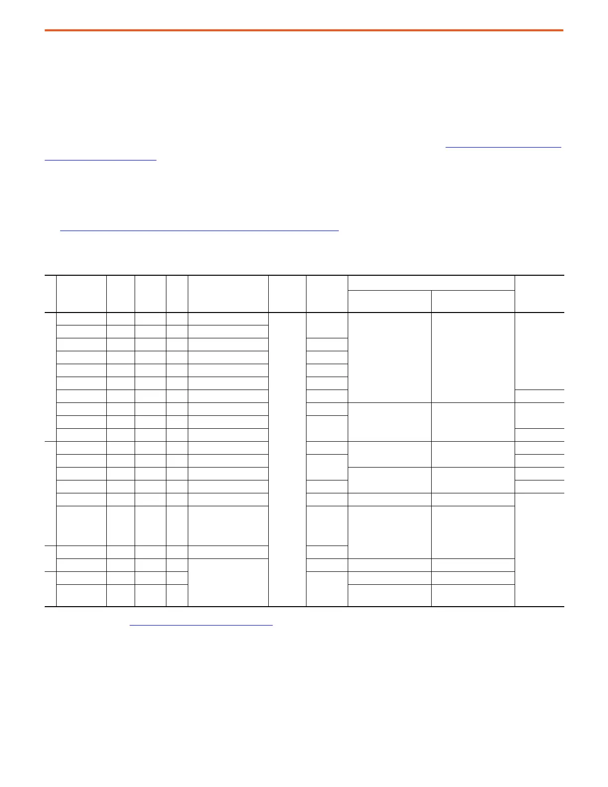
230V AC Input Drives
Frame
Drive Current
Rating Code
DC
Amps
AC Line
Amps
Hp
Dynamic Brake
Resistor Kit Cat. No.
Armature
Voltage
(V)
Total dB
Resistance
(ohms)
DC Loop Contactor Cat. No.
(1)
(1) Coil voltage = 115V AC, 50/60Hz.
DC Contactor
Crimp Lugs
Cat. No.
(2)
(2) For more information, see DC Contactor Crimp Lug Kit Specifications on page 19.
Drive without
Dynamic Brake
Drive with
Dynamic Brake
A
7P0 7 5.7 1.5 1370-DBL62
240
20
1370-NC56 1370-DC56
1370-LG40
9P0 9 7.4 2 1370-DBL63
012 12 9.8 3 1370-DBL64 15
020 20 16 5 1370-DBL65 8.6
029 29 24 7.5 1370-DBL66 6
038 38 31 10 1370-DBL67 5
055 55 45 15 1370-DBL68 3.5 1370-LG56
073 73 60 20 1370-DBL69 2.6
1370-NC110 1370-DC110
1370-LG92
093 93 76 25 1370-DBL70
2
110 110 90 30 1370-DBL71 1370-LG110
B
146 146 119 40 1370-DBL72 1.4
1370-NC180 1370-DC180
1370-LG160
180 180 147 50 1370-DBL73
1
1370-LG180
218 218 178 60 1370-DBL74
1370-NC280 1370-DC280
1370-LG228
265 265 217 75 1370-DBL75 0.67 1370-LG268
360 360 294 100 1370-DBL76 0.47 ABB_EHDB360C2P-1L2S ABB_EHDB360C-1L22SS
(3)
(3) Wire and lug size dependent on enclosure dimensions and local codes.
434 434 355 125
CUTLER-
HAMMER_G3AP50
(Qty 4 - two in series,
two in parallel)
0.4
ABB_EHDB520C2P-1L2S ABB_EHDB520C-1L22SS
C
521 521 426 150 HUBBELL_Y139W322GB 0.322
700 700 572 200
(4)
(4) No dynamic brake resistor kit available for this drive rating—must be sourced locally.
0.25 ABB_EHDB800C2P-1L2S ABB_EHDB800C-1L22SS
D
875 875 715 250
0.2
ABB_EHDB960C2P-1L2S ABB_EHDB960C-1L22SS
1K0 1050 858 300
SIEMENS-MFG_14-193-101-
58-2 (Qty 2)
SIEMENS-MFG_14-193-101-
58-2 (Qty 1)

 Loading...


