38 Rockwell Automation Publication PFLEX-AP005A-EN-P - October 2010
Chapter 1 Drive Selection Considerations
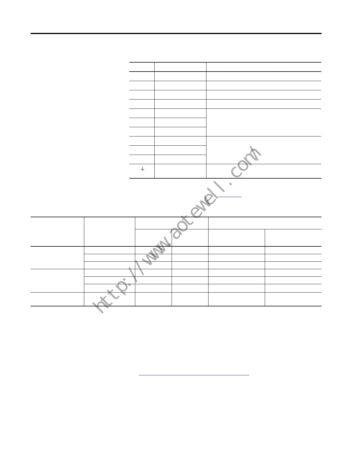
Figure 20 - PowerFlex 750-Series Frames 2…7 Power Terminal Block Designations
Figure 21 - PowerFlex 755 Drive Frame 8 Power Wiring Options
Control Terminal
Comparison
Input/Output
The PowerFlex 700 drive has standard I/O embedded on the main control board.
The voltage of this I/O can be determined by the catalog string position ‘k’.
See PowerFlex Drive Catalog Numbers
on page 46. The PowerFlex 755 drive
contains one digital input on the main control board and uses the optional 750-
Series I/O Modules for additional I/O. The PowerFlex 753 contains some I/O
resident to the main control board and also uses optional I/O.
Terminal Description Notes
+DC DC Bus (+) DC Input Power or Dynamic Brake Chopper
-DC DC Bus (–) DC Input Power or Dynamic Brake Chopper
BR1 DC Brake (+) Dynamic Brake Resistor Connection (+)
BR2 DC Brake (–) Dynamic Brake Resistor Connection (–)
U U (T1) Motor Connections
(1)
(1) Important: Motors with NEMA MG1 Part 31.40.4.2 inverter grade insulation systems are recommended. If you
intend to connect a motor that is not rated inverter grade, refer to Wiring and Grounding Guidelines for Pulse
Width Modulated (PWM) AC Drives, publication DRIVES-IN001
, for recommendations.
VV (T2)
WW (T3)
R R (L1) AC Line Input Power
SS (L2)
T T (L3)
PE / PE Ground Terminating point to chassis ground for incoming AC line
and motor shield.
Cable Option
Wire Entry/Exit
Location
IP20, NEMA/UL Type 1 Drive
(2500 MCC Style Cabinet)
IP20, NEMA/UL Type 1 Drive and Cabinet Options
(2500 MCC Style Cabinet)
600 mm (23.6 in.)
Deep Drive Bay
800 mm (31.5 in.)
Deep Drive Bay
600 or 800 mm Deep Drive
Bay w/600 mm Wide Wiring
Only Bay
600 or 800 mm Deep Drive
Bay w/600 mm Cabinet
Options Bay
Armored Cable with
Conduit Hubs
Top Entry, Bottom Exit
✓✓ ✓
Bottom Entry, Bottom Exit
✓✓
Top Entry,Top Exit
✓✓
Shielded Cable with
Conduit Hubs
Top Entry, Bottom Exit
✓✓ ✓ ✓
Bottom Entry, Bottom Exit
✓✓
Top Entry,Top Exit
✓✓
✓
(2)
Shielded Cable without
Conduit Hubs
(1)
Bottom Entry, Bottom Exit
✓✓ ✓
(1) Other configurations with shielded cable are possible but using conduit hubs is recommended.
(2) This wiring configuration is possible when there are no ouput options in the option bay and the motor connections are wired from the drive bay.

 Loading...


