Rockwell Automation Publication PFLEX-AP005A-EN-P - October 2010 45
Drive Selection Considerations Chapter 1
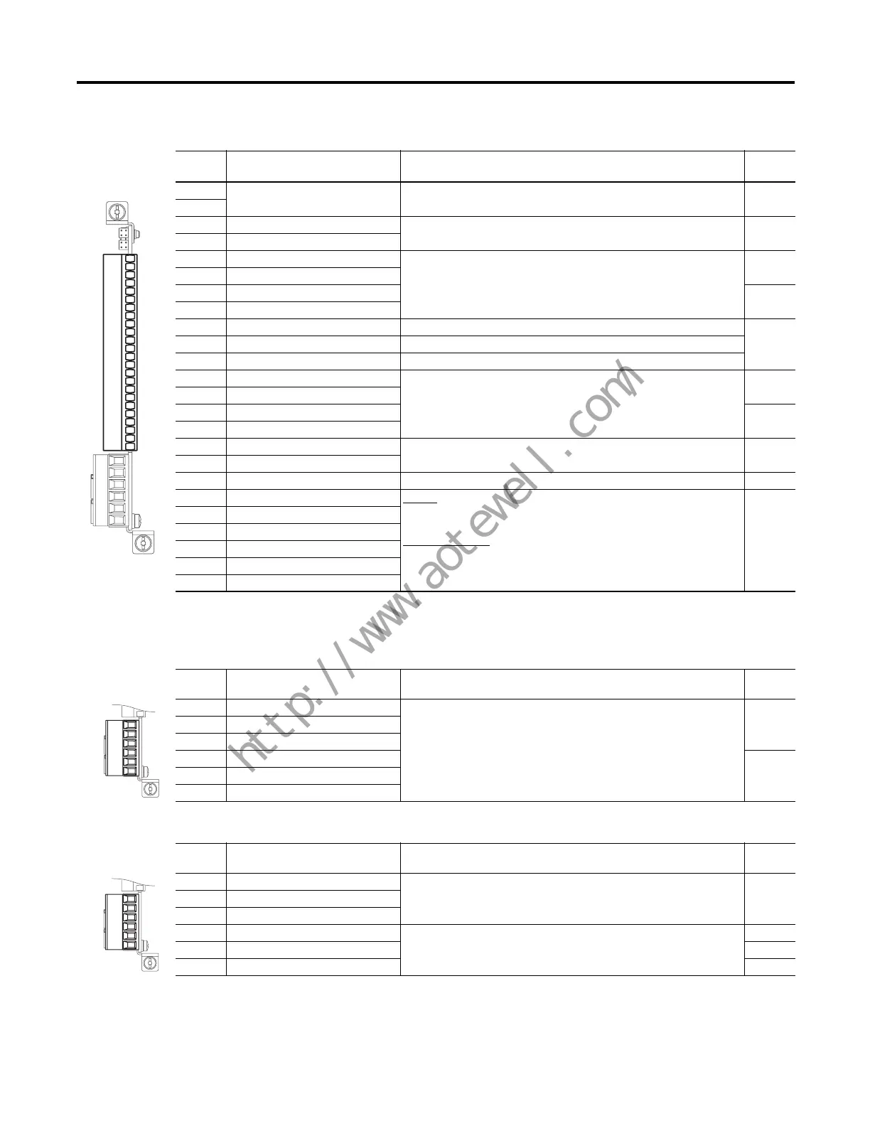
Table 22 - TB1 Control Terminal Designations
Table 23 - TB2 Terminal Designations (Cat. Nos. 20-750-2262x-2R)
(1)
Table 24 - TB2 Terminal Designations (Cat. No. 20-750-2263C-1R2T)
(1)
Terminal Name Description
Related
Param.
Sh Shield Terminating point for wiring shields when an EMC plate or conduit box is
not installed
Sh
Ptc– Motor PTC (–) Motor protection device (Positive Temperature Coefficient) 40
Ptc+ Motor PTC (+)
Ao0– Analog Out 0 (–) Bipolar, ±10V, 11 bit & sign, 2 k ohm minimum load;
4-20 mA, 11 bit & sign, 400 ohm maximum load
75
Ao0+ Analog Out 0 (+)
Ao1– Analog Out 1 (–) 85
Ao1+ Analog Out 1 (+)
–10V –10 Volt Reference 2k ohm minimum
10VC 10 Volt Common For (–) and (+) 10 Volt references
+10V +10 Volt Reference 2k ohm minimum
Ai0– Analog Input 0 (–) Isolated
(2)
, bipolar, differential, ±10V, 11 bit & sign, 88k ohm input
impedance
50, 70
Ai0+ Analog Input 0 (+)
Ai1– Analog Input 1 (–) 60, 70
Ai1+ Analog Input 1 (+)
24VC 24 Volt Common Drive supplied logic input power
200 mA max
+24V +24 Volt DC
Di C Digital Input Common Common for Digital Inputs 0…5
Di 0 Digital Input 0
(1)
24V DC - Opto isolated
Low State: less than 5V DC
High State: greater than 20V DC 11.2 mA DC
115V AC, 50/60 Hz
- Opto isolated
Low State: less than 30V AC
High State: greater than 100V AC
1
Di 1 Digital Input 1
(1)
Di 2 Digital Input 2
(1)
Di 3 Digital Input 3
(1)
Di 4 Digital Input 4
(1)
Di 5 Digital Input 5
(1)
(1) Digital Inputs are either 24 Volts DC (2262C) or 115 Volts AC (2262D) based on module catalog number. Ensure applied voltage is correct for I/O module.
(2) Differential Isolation—external source must be maintained at less than 160V with respect to PE. Input provides high common mode immunity.
Sh
Sh
Ptc–
Ptc+
Ao0–
Ao0+
Ao1–
Ao1+
–10V
10VC
+10V
Ai0–
Ai0+
Ai1–
Ai1+
24VC
+24V
Di C
Di 0
Di 1
Di 2
Di 3
Di 4
Di 5
(1) -2R suffix signifies two relays and -1R2T signifies one relay and two transistor outputs.
Terminal Name Description
Related
Param.
R0NO Relay 0 N.O. Relay contact output
Rating: 240V AC or 24V DC = 2 A max.
Inductive/Resistive
10
R0C Relay 0 Common
R0NC Relay 0 N.C.
R1NO Relay 1 N.O. 20
R1C Relay 1 Common
R1NC Relay 1 N.C.
R0NO
R0C
R0NC
R1NO
R1C
R1NC
Terminal Name Description
Related
Param.
R0NO Relay 0 N.O. Relay contact output
Rating: 240V AC or 24V DC = 2 A max.
Inductive/Resistive
10
R0C Relay 0 Common
R0NC Relay 0 N.C.
T0 Transistor Output 0 Transistor output
Rating: 24V DC = 1 A max.
Resistive
20
TC Transistor Output Common
T1 Transistor Output 1 30
R0NO
R0C
R0NC
TO
TC
T1

 Loading...


