EasyManuals Logo
Home>Rockwell Automation>Controller>MicroLogix 1100 Series

Rockwell Automation MicroLogix 1100 Series User Manual

Rockwell Automation MicroLogix 1100 Series
34 pages
To Next Page IconTo Next Page
To Previous Page IconTo Previous Page
Page #10 background imageLoading...
Page #10 background image
12
Publication 1763-IN001C-EN-P - June 2015
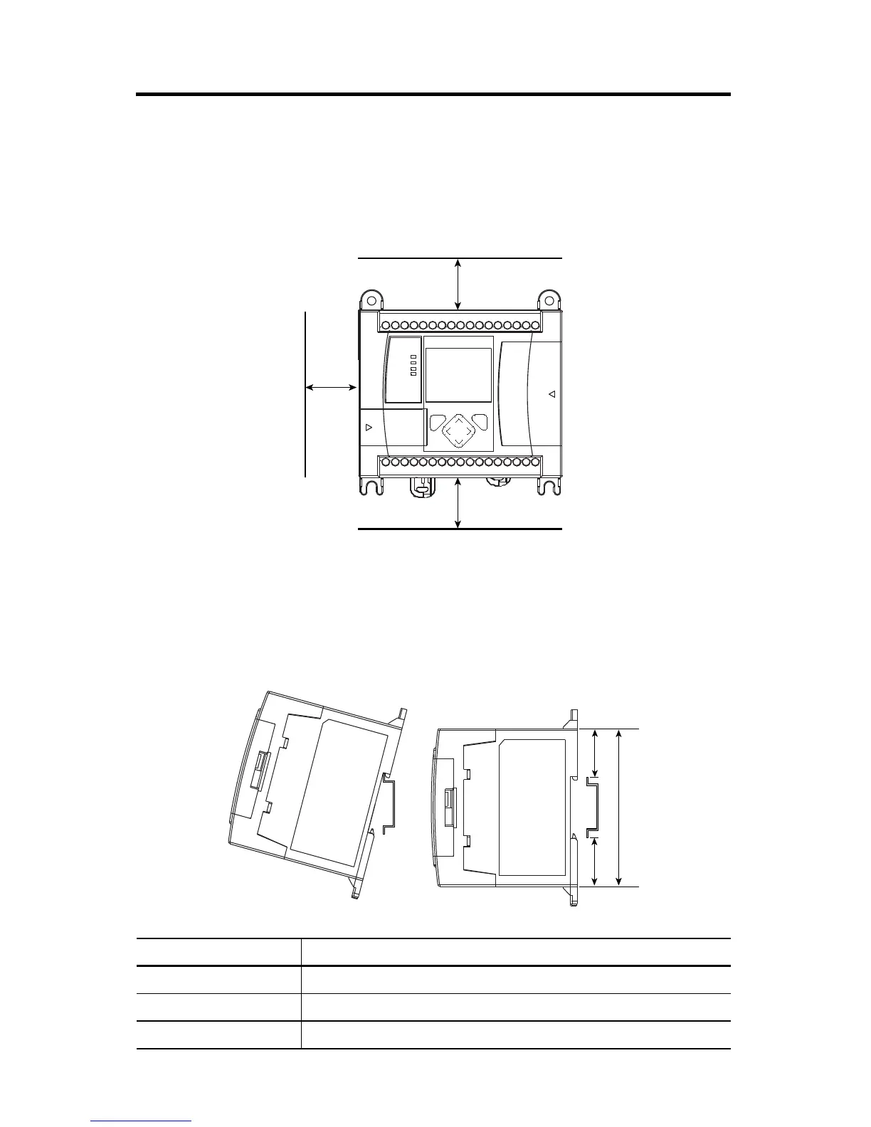
Controller Spacing
The controller mounts horizontally, with the expansion I/O extending to the right of the
controller. Allow 50 mm (2 in.) of space on all but the right side for adequate ventilation, as
shown below.
DIN Rail Mounting
The maximum extension of the latch is 14 mm (0.55 in.) in the open position. A flat-blade
screwdriver is required for removal of the controller. The controller can be mounted to
EN50022-35x7.5 or EN50022-35x15 DIN rails. DIN rail mounting dimensions are shown
below.
Dimension Height
A 90 mm (3.5 in.)
B 27.5 mm (1.08 in.)
C 27.5 mm (1.08 in.)
ESC OK
Top
Side
Bottom

Questions and Answers:

Question and Answer IconNeed help?

Do you have a question about the Rockwell Automation MicroLogix 1100 Series and is the answer not in the manual?

Rockwell Automation MicroLogix 1100 Series Specifications

General IconGeneral
BrandRockwell Automation
ModelMicroLogix 1100 Series
CategoryController
LanguageEnglish

Related product manuals