C-22
VSM500 DeviceNet Option Board
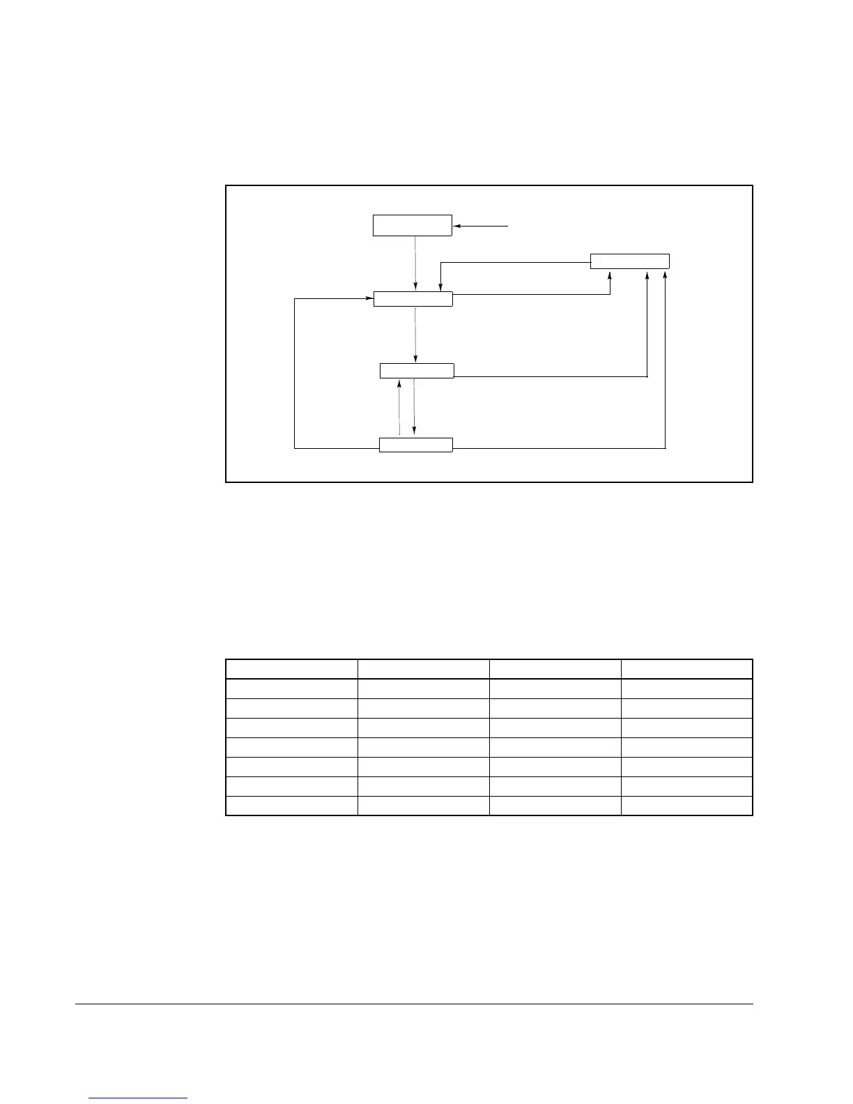
State Transition Diagram
The following State Transition Diagram provides a graphical description of the states
and state transitions that are reflected in attribute #6.
Run/Stop Event Matrix
Attribute 5, NetCtrl, is used to request that Run/Stop events be controlled from the
network. Before Run/Stop control is accomplished from the network, Attribute 15,
CtrlFromNet must be set to 1 by the device in response to a NetCtrl request.
If attribute 15, CtrlFromNet is set to 1, the events Run and Stop are triggered by a
combination of the RunFwd and RunRev attributes as shown in the following table.
Important: When attempting to use attribute 3 or 4 to start the drive, the Explicit
Message connection (Class 5, instance 1) attribute 9, Expected Packet
Rate must be set to greater than zero.
Figure C.1 – State Transition Diagram
RunFwd RunRev Trigger Event Run Type
00StopNA
0 -> 1 0 Run RunFwd
0 0 -> 1 Run RunRev
0 -> 1 0 -> 1 No Action NA
1 1 No Action NA
1->0 1 Run RunRev
1 1->0 Run RunFwd
Switch Power On
Ready
Enabled
Faulted
Switch Power Off
Fault Reset
Fault Detected
Fault Detected
Stop Complete
Run
Non-Existent
Stopping
Fault Detected
No Run
Run
 Loading...