Flags are logical registers which exist in controller’s memory. Each Flag represent a status of relevant situation
which may occur on controller. For example if a user enters a DURESS PIN code this will activate (sets ON) the
DURESS flag, when controller recognizes triggering of the TAMPER input it will trigger (sets ON) the TAMPER
flag etc.
The PR311 utilizes the following flags:
AUX1 Flag
LIGHT Flag
TAMPER Flag
DURESS Flag
TROUBLE Flag
Depending on a type of the Flag it can be set or cleared by various situations (see table below). Every Flag has
assigned a Timer. The Timer specifies for what time the relevant Flag will remain active after it is set ON. The
Flag Timer can be programmed in seconds [SS] or minutes [MM]. The Timers for AUX1 and LIGHT flags can be
optionally programmed to a value SS=00 (operation in Latch mode), in this case once the Flag is set it will
remain in ON mode for unlimited time till the moment when adequate command or other event will occur which
will clear it.
Table 2: System Flags
Flag Latch
Mode
Setting methods Clearing methods
AUX1 Yes
SS=00
User command (function 31)
From input line (code 71 and 73)
User command (function 31)
From input line (code 72 and 73)
LIGHT Yes
SS=00
User command (function 33)
Input line (code 68 and 70)
Function key (code F2)
User command (function 33)
Input line (code 69 and 70)
TAMPER No Input line (code 08) Disarming of the controller
DURESS No DURESS code entry Disarming of the controller
TROUBLE No Lost of communication with XM-2 module
AC Lost input (code 05) triggered
Low Battery input (code 06) triggered
Disarming of the controller
Note: All Flags are automatically cleared in following situations: after controller’s restart, after entry to the
Installer Programming or when controller is being programmed from a PC.
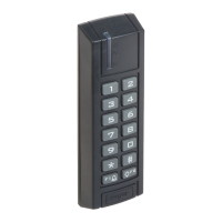
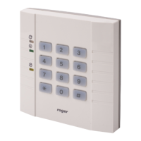
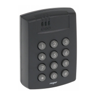
4.13 Operation with External PRT Series Reader
The PR311 is capable to operate with external PRT series reader. If used the PRT reader enables two-way door
control. The PRT reader should be connected to controller’s CLK and DTA lines and must have an address set to
ID=0. The maximum distance between controller and the PRT reader is limited to 150m.
4.14 Operation with XM-2 I/O Extension Module
The PR311 is capable to operate with external XM-2 I/O extension module. If used the XM-2 adds two inputs
and two relay outputs to a controller. Each input and output of the XM-2 can be programmed on the same basis
as internal inputs and outputs of a controller. The XM-2 should be connected to controller’s CLK and DTA lines
and should have address set to ID=5. The maximum distance between a controller and the XM-2 extension
module is limited to 150m.
4.15 Alarms
The PR311 controller has been designed to detect and indicate the following alarm types:
Forced Door
Prealarm
Door Ajar
The alarm signaling is carried out over the dedicated output line. Each alarm can be signaled on separate
output or alternatively the one output line can be configured to signal two or even three alarms. The alarm
signaling the PR311 uses different signal modulation of an output, depending on alarm type (see table below).
Alarm duration is ~3 minutes, regardless of alarm type. Each alarm can be stopped manually within 3 minutes
from its start by using valid identifier. Additionally, a Door Ajar alarm is stopped as soon as the door is closed.
If more than one alarm is triggered, the reader indicates the alarm with the highest priority.