PR311 v1.0 fv102 EN Rev.E.DOC 10/22/2007
19
6 I NSTALLATION AND S ETUP G UIDELINES
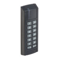
The PR311 reader should be mounted near the supervised door on a vertical piece of supporting
structure.
Assure that the surface beneath of the controller’s rear panel is flat and smooth, especially in the area
where tamper sensor will contact a surface of the wall.
Disconnect power supply before making any electrical connections.
For installations on a metal surface, place a non-metallic min. 10 mm thick spacer (a plastic/plaster
plate etc.) between the reader and the supporting structure.
For installations with two readers to be mounted on opposite sides of the same wall and aligned along
the same geometrical axis, place a metal plate between them and make sure none of them has direct
contact with it (allow min. 10 mm space ).
For best results mount the proximity readers at least 0.5 m apart.
When using separate power supply sources, connect all power supply negative (–) leads together.
Roger recommends to ground the negative (–) power supply lead.
With its relatively weak electromagnetic field generation, the terminal should not cause any harmful
interference to operation of other equipment. However, its card reading performance can be affected by
other interference generating devices, esp. radio waves emitting equipment or CRT computer monitors.
If card reading performance of the controller deteriorates (e.g. reduced reading range or incorrect
readings) consider reinstallation in a new location.
Once installed and electrically connected, the reader has to be properly configured. The programming
can be carried out either through manual method or from PC. A new factory unit is delivered with
preprogrammed MASTER card and with address set to ID=00.
When lost, MASTER or INSTALLER cards can be reprogrammed to a reader anew, any EM 125 kHz card
can be programmed as a MASTER or an INSTALLER card. If required the MASTER users and/or
INSTALLER user can be programmed as a PIN code only, Card only or as both a Card and a PIN.
It is strongly recommended to program the controller form one source only: from PC program or
manually. When both methods are used to the same unit it may result in some confusion (e.g. new user
added manually will not exist in PC program).
When controller is intended to be managed from PC only you don’t have to program any MASTER or
INSTALLER card/PIN, just program ID address of the unit and connect it to the computer.
When controller operates in an Integrated Access Control System it must be connected to RS485
communication bus.
The communication bus can be laid down using free topology – bus, star, three or any combination of
them. It is forbidden to use topology of a ring.
Generally the twisted, unshielded cables are recommended for communication bus (popular UTP cables).
No terminating resistors on the ends of communication bus are required.
The maximum cable run between any controller on the communication bus and a host PC must not
exceed 1200m.
The maximum cable run between controller and external unit(s) connected to Clock and Data lines (e.g.
external reader or I/O extension module) can be maximum 150m long.
The controller must be supplied form reliable power supply, calculate the adequate wire gauge to
guarantee that the voltage dropout between the power supply and the supplied unit doesn’t exceed 1V
in the worst case.
It is recommended to supply door release device (e.g. door strike or magnet lock) from separate power
supply. When both controller and door release device are supplied from the same power source you
must use separate cable pairs for both of them.
Always add the silicon diode (e.g. 1N400x series) in parallel to door release device – locate diode as
close as possible to door release and as far as possible from the controller.
Do not supply the door release from the supply terminals of a controller.