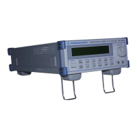
Unit Description Power Supply NGMO
4.00 / 07-2004 3-7
3.4 Function Description
3.4.1 Communication
Fig. 3-3 NGMO2, Pin codes
Channel Relay Connector, rear panel, SUB 15, male
Pin Function Pin Function Signal
1 DVM- 1 RELOUT 1 output, relay driver, open collector 28 VDC/200 mA
2 DVM+ 2 RELOUT 2 output, relay driver, open collector 28 VDC/200 mA
3 FORCE- 3 RELOUT 3 output, relay driver, open collector 28 VDC/200 mA
4 FORCE- 4 RELOUT 4 output, relay driver, open collector 28 VDC/200 mA
5 SENSE- 5 FAULT output, fault signal, open collector 28 VDC/200 mA
6 SENSE+ 6 NC not used not used
7 FORCE+ 7 NC not used not used
8 FORCE+ 8 GND GND signal GND
9 GND GND signal GND
10 INHIBIT_B input, external inhibit signal TTL 0 ... 12 VDC
11 TRIGGER_B input, external inhibit signal TTL 0 ... 12 VDC
12 INHIBIT_A input, external inhibit signal TTL 0 ... 12 VDC
13 TRIGGER_A input, external inhibit signal TTL 0 ... 12 VDC
14 COMPL_B output, complete signal, open
collector
28 VDC/200 mA
max.
15 COMPL_A output, complete signal, open
collector
28 VDC/200 mA
max.

 Loading...